Team Project (tP):
Week 11 [Fri, Oct 23rd] - Topics
Detailed Table of Contents
- [W11.1] More Design Patterns
-
[W11.1a] Design → Design Patterns → MVC Pattern → What
-
[W11.1b] Design → Design Patterns → Observer Pattern → What
-
[W11.1c] Design → Design Patterns → Other design patterns : OPTIONAL
-
[W11.1d] Design → Design Patterns → Combining design patterns : OPTIONAL
-
[W11.1e] Design → Design Patterns → Using design patterns : OPTIONAL
-
[W11.1f] Design → Design Patterns → Design patterns versus design principles : OPTIONAL
-
[W11.1g] Design → Design Patterns → Other types of patterns : OPTIONAL
- [W11.2] Architectural Styles
-
[W11.2a] Design → Architecture → Styles → What
-
[W11.2b] Design → Architecture → Styles → n-Tier Style → What
-
[W11.2c] Design → Architecture → Styles → Client-Server Style → What
-
[W11.2d] Design → Architecture → Styles → Event-Driven Style → What
-
[W11.2e] Design → Architecture → Styles → Transaction Processing Style → What
-
[W11.2f] Design → Architecture → Styles → Service-Oriented Style → What
-
[W11.2g] Design → Architecture → Styles → Using styles
-
[W11.2h] Design → Architecture → Styles → More styles : OPTIONAL
- [W11.3] Test Cases: Combining Multiple Inputs
-
[W11.3a] Quality Assurance → Test Case Design → Combining Test Inputs → Why
-
[W11.3b] Quality Assurance → Test Case Design → Combining Test Inputs → Test input combination strategies
-
[W11.3c] Quality Assurance → Test Case Design → Combining Test Inputs → Heuristic: Each valid input at least once in a positive test case
-
[W11.3d] Quality Assurance → Test Case Design → Combining Test Inputs → Heuristic: No more than one invalid input in a test case
-
[W11.3e] Quality Assurance → Test Case Design → Combining Test Inputs → Mix
- [W11.4] Other QA Techniques
- [W11.5] Reuse
APIs
-
[W11.5a] Implementation → Reuse → Introduction → What
-
[W11.5b] Implementation → Reuse → Introduction → When
Libraries
-
[W11.5c] Implementation → Reuse → Libraries → What
-
[W11.5d] Implementation → Reuse → Libraries → How
-
[W11.5e] Implementation → Reuse → APIs → What
Frameworks
-
[W11.5f] Implementation → Reuse → Frameworks → What
-
[W11.5g] Implementation → Reuse → Frameworks → Frameworks versus libraries
Platforms
- [W11.5h] Implementation → Reuse → Platforms → What
- [W11.6] Cloud Computing : OPTIONAL
- [W11.7] Other UML Models : OPTIONAL
-
[W11.7a] Design → Modelling → Modelling Behaviors Communication diagrams : OPTIONAL
-
[W11.7b] Design → Modelling → Modelling Behaviors State machine diagrams : OPTIONAL
-
[W11.7c] Design → Modelling → Modelling Structure → Deployment diagrams : OPTIONAL
-
[W11.7d] Design → Modelling → Modelling Structure → Component diagrams : OPTIONAL
-
[W11.7e] Design → Modelling → Modelling Structure → Package diagrams : OPTIONAL
-
[W11.7f] Design → Modelling → Modelling Structure → Composite structure diagrams : OPTIONAL
-
[W11.7g] Design → Modelling → Modelling Behaviors Timing diagrams : OPTIONAL
-
[W11.7h] Design → Modelling → Modelling Behaviors Interaction overview diagrams : OPTIONAL
Guidance for the item(s) below:
Previously, you learned about design patterns, and a some example design patterns. Let's continue that journey this week.
Guidance for the item(s) below:
First, let's learn two more widely-cited design patterns.
Design → Design Patterns → MVC Pattern → What
Can explain the Model View Controller (MVC) design pattern
Context
Most applications support storage/retrieval of information, displaying of information to the user (often via multiple UIs having different formats), and changing stored information based on external inputs.
Problem
The high coupling that can result from the interlinked nature of the features described above.
Solution
Decouple data, presentation, and control logic of an application by separating them into three different components: Model, View and Controller.
- View: Displays data, interacts with the user, and pulls data from the model if necessary.
- Controller: Detects UI events such as mouse clicks and button pushes, and takes follow up action. Updates/changes the model/view when necessary.
- Model: Stores and maintains data. Updates the view if necessary.
The relationship between the components can be observed in the diagram below. Typically, the UI is the combination of View and Controller.

Given below is a concrete example of MVC applied to a student management system. In this scenario, the user is retrieving the data of a student.
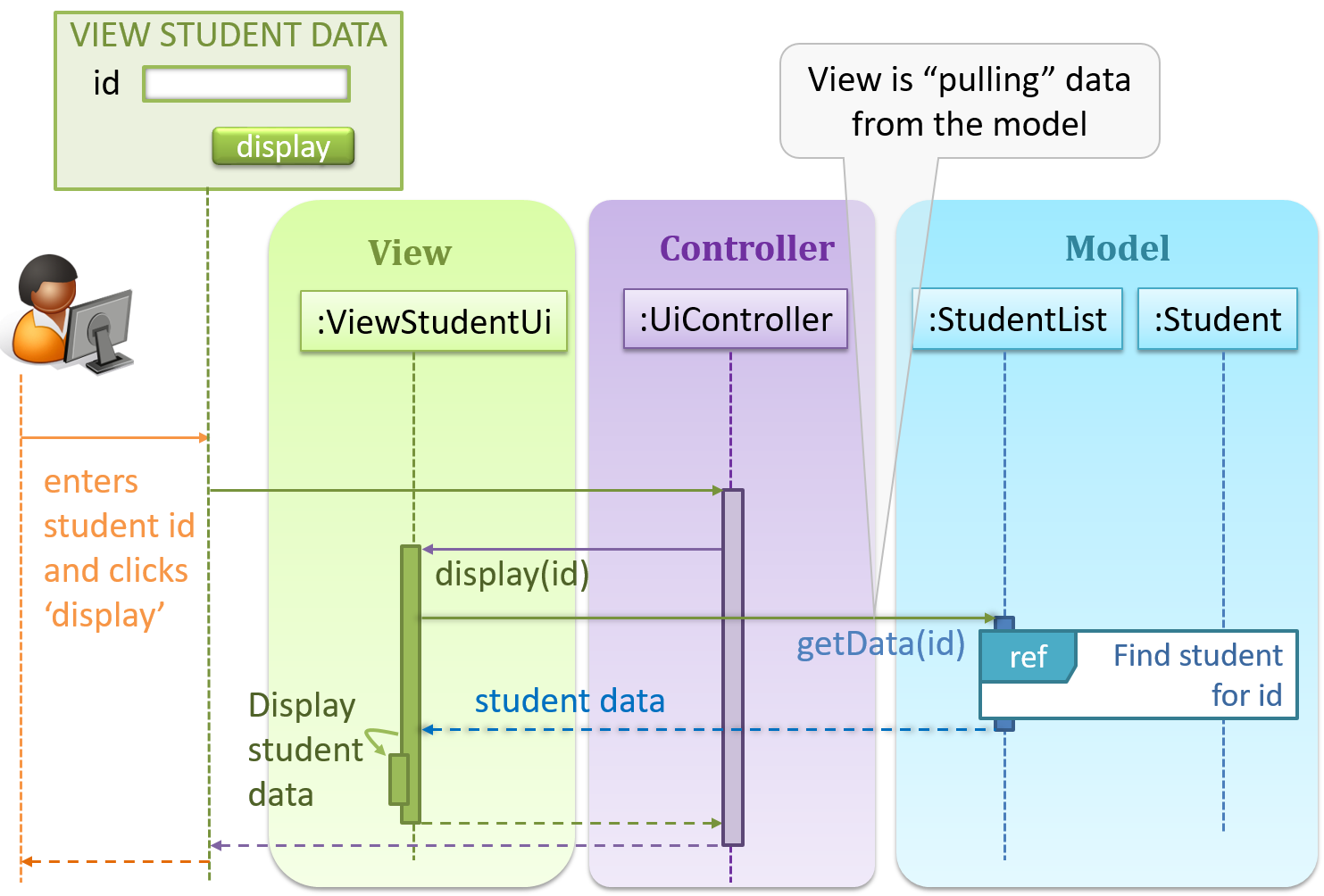
In the diagram above, when the user clicks on a button using the UI, the ‘click’ event is caught and handled by the UiController. The ref frame indicates that the interactions within that frame have been extracted out to another separate sequence diagram.
Note that in a simple UI where there’s only one view, Controller and View can be combined as one class.
There are many variations of the MVC model used in different domains. For example, the one used in a desktop GUI could be different from the one used in a web application.
Design → Design Patterns → Observer Pattern → What
Can explain the Observer design pattern
Context
An object (possibly more than one) is interested in being notified when a change happens to another object. That is, some objects want to ‘observe’ another object.
Consider this scenario from a student management system where the user is adding a new student to the system.

Now, assume the system has two additional views used in parallel by different users:
StudentListUi: that accesses a list of students andStudentStatsUi: that generates statistics of current students.
When a student is added to the database using NewStudentUi shown above, both StudentListUi and StudentStatsUi should get updated automatically, as shown below.
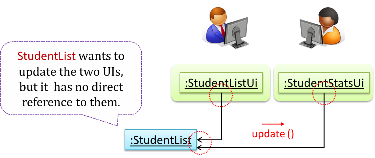
However, the StudentList object has no knowledge about StudentListUi and StudentStatsUi (note the direction of the navigability) and has no way to inform those objects. This is an example of the type of problem addressed by the Observer pattern.
Problem
The ‘observed’ object does not want to be coupled to objects that are ‘observing’ it.
Solution
Force the communication through an interface known to both parties.

Here is the Observer pattern applied to the student management system.
During the initialization of the system,
-
First, create the relevant objects.
StudentList studentList = new StudentList();
StudentListUi listUi = new StudentListUi();
StudentStatsUi statsUi = new StudentStatsUi(); -
Next, the two UIs indicate to the
StudentListthat they are interested in being updated wheneverStudentListchanges. This is also known as ‘subscribing for updates’.studentList.addUi(listUi);
studentList.addUi(statsUi); -
Within the
addUioperation ofStudentList, all Observer object subscribers are added to an internal data structure calledobserverList.// StudentList class
public void addUi(Observer o) {
observerList.add(o);
}
Now, whenever the data in StudentList changes (e.g. when a new student is added to the StudentList),
-
All interested observers are updated by calling the
notifyUIsoperation.// StudentList class
public void notifyUIs() {
// for each observer in the list
for (Observer o: observerList) {
o.update();
}
} -
UIs can then pull data from the
StudentListwhenever theupdateoperation is called.// StudentListUI class
public void update() {
// refresh UI by pulling data from StudentList
}Note that
StudentListis unaware of the exact nature of the two UIs but still manages to communicate with them via an intermediary.
Here is the generic description of the observer pattern:

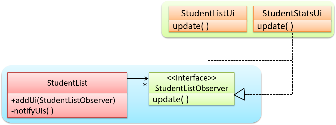
<<Observer>>is an interface: any class that implements it can observe an<<Observable>>. Any number of<<Observer>>objects can observe (i.e. listen to changes of) the<<Observable>>object.- The
<<Observable>>maintains a list of<<Observer>>objects.addObserver(Observer)operation adds a new<<Observer>>to the list of<<Observer>>s. - Whenever there is a change in the
<<Observable>>, thenotifyObservers()operation is called that will call theupdate()operation of all<<Observer>>s in the list.
In a GUI application, how is the Controller notified when the “save” button is clicked? UI frameworks such as JavaFX have inbuilt support for the Observer pattern.
Exercises
Polymorphism and the Observer pattern
Explain how polymorphism is used in the Observer pattern.

With respect to the general form of the Observer pattern given above, when the Observable object invokes the notifyObservers() method, it is treating all ConcreteObserver objects as a general type called Observer and calling the update() method of each of them. However, the update() method of each ConcreteObserver could potentially show different behavior based on its actual type. That is, the update() method shows polymorphic behavior.
In the example given below, the notifyUIs operation can result in StudentListUi and StudentStatsUi changing their views in two different ways.
Observer pattern usage
The Observer pattern can be used when you want one object to initiate an activity in another object without having a direct dependency from the first object to the second object.
True
Explanation: Yes. For example, when applying the Observer pattern to an MVC structure, Views can get notified and update themselves about a change to the Model without the Model having to depend on the Views.
Guidance for the item(s) below:
Given below are a few more topics that continue the theme of design patterns, but have been made optional to reduce the module workload.
Design → Design Patterns → Other design patterns
Can recognize some of the GoF design patterns
The most famous source of design patterns is the "Gang of Four" (GoF) book which contains 23 design patterns divided into three categories:
- Creational: About object creation. They separate the operation of an application from how its objects are created.
- Abstract Factory, Builder, Factory Method, Prototype, Singleton
- Structural: About the composition of objects into larger structures while catering for future extension in structure.
- Adapter, Bridge, Composite, Decorator, Façade, Flyweight, Proxy
- Behavioral: Defining how objects interact and how responsibility is distributed among them.
- Chain of Responsibility, Command, Interpreter, Template Method, Iterator, Mediator, Memento, Observer, State, Strategy, Visitor
Design → Design Patterns → Combining design patterns
Can combine multiple patterns to fit a context
Design patterns are usually embedded in a larger design and sometimes applied in combination with other design patterns.
Let us look at a case study that shows how design patterns are used in the design of a class structure for a Stock Inventory System (SIS) for a shop. The shop sells appliances and accessories for the appliances. SIS simply stores information about each item in the store.
Use Cases:
- Create a new item
- View information about an item
- Modify information about an item
- View all available accessories for a given appliance
- List all items in the store
SIS can be accessed using multiple terminals. Shop assistants use their own terminals to access SIS, while the shop manager’s terminal continuously displays a list of all items in the store. In the future, it is expected that suppliers of items use their own applications to connect to SIS to get real-time information about the current stock status. User authentication is not required for the current version, but may be required in the future.
A step by step explanation of the design is given below. Note that this is one out of many possible designs. Design patterns are also applied where appropriate.
A StockItem can be an Appliance or an Accessory.

To track that each Accessory is associated with the correct Appliance, consider the following alternative class structures.

The third one seems more appropriate (the second one is suitable if accessories can have accessories). Next, consider between keeping a list of Appliances, and a list of StockItems. Which is more appropriate?

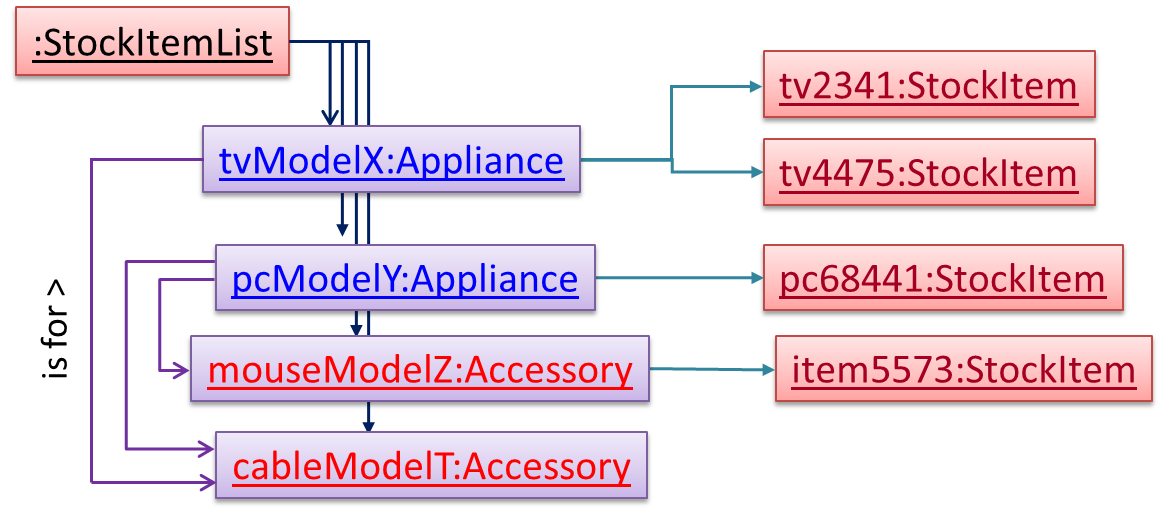
The latter seems more suitable because it can handle both appliances and accessories the same way. Next, an abstraction occurrence pattern is applied to keep track of StockItems.

Note the inclusion of navigabilities. Here’s a sample object diagram based on the class model created thus far.
Next, apply the façade pattern to shield the SIS internals from the UI.

As UI consists of multiple views, the MVC pattern is applied here.
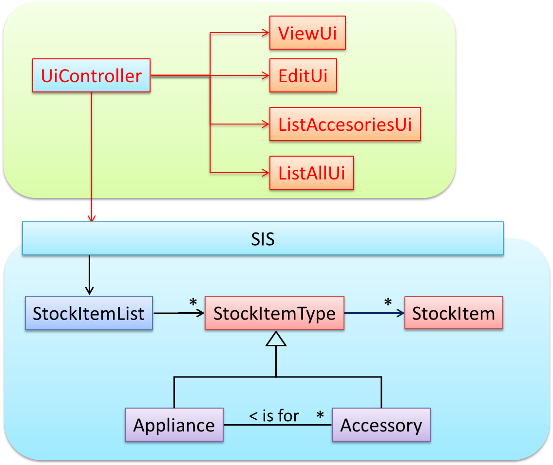
Some views need to be updated when the data changes; apply the Observer pattern here.

In addition, the Singleton pattern can be applied to the façade class.
Design → Design Patterns → Using design patterns
Can explain pros and cons of design patterns
Design patterns provide a high-level vocabulary to talk about design.
Someone can say 'apply Observer pattern here' instead of having to describe the mechanics of the solution in detail.
Knowing more patterns is a way to become more ‘experienced’. Aim to learn at least the context and the problem of patterns so that when you encounter those problems you know where to look for a solution.
Some patterns are domain-specific e.g. patterns for distributed applications, some are created in-house e.g. patterns in the company/project and some can be self-created e.g. from past experience.
Be careful not to overuse patterns. Do not throw patterns at a problem at every opportunity. Patterns come with overhead such as adding more classes or increasing the levels of abstraction. Use them only when they are needed. Before applying a pattern, make sure that:
- there is substantial improvement in the design, not just superficial.
- the associated tradeoffs are carefully considered. There are times when a design pattern is not appropriate (or an overkill).
Design → Design Patterns → Design patterns versus design principles
Can differentiate between design patterns and principles
Design principles have varying degrees of formality – rules, opinions, rules of thumb, observations, and axioms. Compared to design patterns, principles are more general, have wider applicability, with correspondingly greater overlap among them.
Design → Design Patterns → Other types of patterns
Can explain how patterns exist beyond the domain of software design
The notion of capturing design ideas as "patterns" is usually attributed to Christopher Alexander. He is a building architect noted for his theories about design. His book The Timeless Way of Building talks about "design patterns" for constructing buildings.
Here is a sample pattern from that book:
When a room has a window with a view, the window becomes a focal point: people are attracted to the window and want to look through it. The furniture in the room creates a second focal point: everyone is attracted toward whatever point the furniture aims them at (usually the center of the room or a TV). This makes people feel uncomfortable. They want to look out the window, and toward the other focus at the same time. If you rearrange the furniture, so that its focal point becomes the window, then everyone will suddenly notice that the room is much more “comfortable”.
Apparently, patterns and anti-patterns are found in the field of building architecture. This is because they are general concepts applicable to any domain, not just software design. In software engineering, there are many general types of patterns: Analysis patterns, Design patterns, Testing patterns, Architectural patterns, Project management patterns, and so on.
In fact, the abstraction occurrence pattern is more of an analysis pattern than a design pattern, while MVC is more of an architectural pattern.
New patterns can be created too. If a common problem that needs to be solved frequently leads to a non-obvious and better solution, it can be formulated as a pattern so that it can be reused by others. However, don’t reinvent the wheel; the pattern might already exist.
Exercises
Give a pattern from another domain
Here are some common elements of a design pattern: Name, Context, Problem, Solution, Anti-patterns (optional), Consequences (optional), other useful information (optional).
Using similar elements, describe a pattern that is not a design pattern. It must be a pattern you have noticed, not a pattern already documented by others. You may also give a pattern not related to software.
Some examples:
- A pattern for testing textual UIs.
- A pattern for striking a good bargain at a mall such as Sim-Lim Square.
Guidance for the item(s) below:
The next topic is like 'design patterns at architecture level'. In fact, the MVC pattern you saw earlier comes close to this category too.
Design → Architecture → Styles → What
Design → Architecture → Introduction → What
Can explain architectural styles
Software architectures follow various high-level styles (aka architectural patterns), just like how building architectures follow various architecture styles.
n-tier style, client-server style, event-driven style, transaction processing style, service-oriented style, pipes-and-filters style, message-driven style, broker style, ...
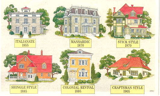
source: https://inspectapedia.com
Design → Architecture → Styles → n-Tier Style → What
Can identify n-tier architectural style
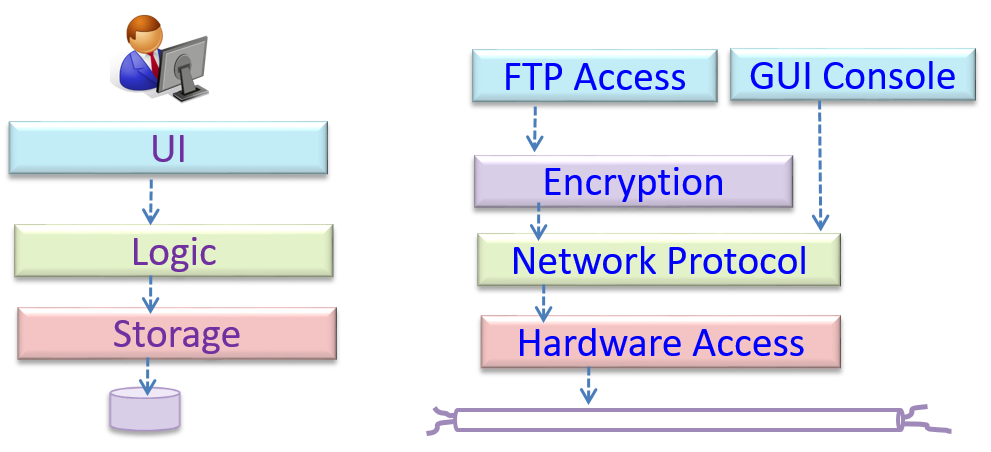
In the n-tier style, higher layers make use of services provided by lower layers. Lower layers are independent of higher layers. Other names: multi-layered, layered.
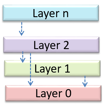
Operating systems and network communication software often use n-tier style.
Design → Architecture → Styles → Client-Server Style → What
Can identify the client-server architectural style
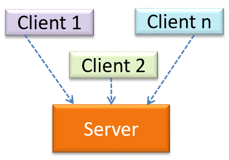
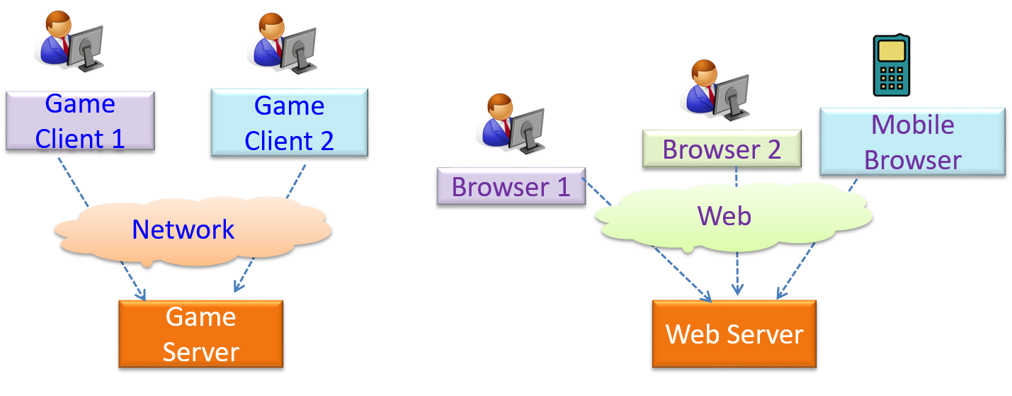
The client-server style has at least one component playing the role of a server and at least one client component accessing the services of the server. This is an architectural style used often in distributed applications.
The online game and the web application below use the client-server style.
Design → Architecture → Styles → Event-Driven Style → What
Can identify event-driven architectural style
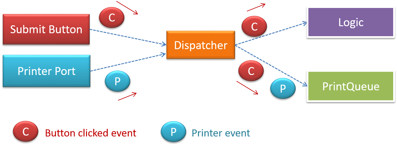
Event-driven style controls the flow of the application by detecting An event is a notable occurrence that happens inside or outside the software, such as the user clicking a button, a timer running out, minimizing a window, etc.events from event emitters and communicating those events to interested event consumers. This architectural style is often used in GUIs.

When the ‘button clicked’ event occurs in a GUI, that event can be transmitted to components that are interested in reacting to that event. Similarly, events detected at a printer port can be transmitted to components related to operating the printer. The same event can be sent to multiple consumers too.
Design → Architecture → Styles → Transaction Processing Style → What
Can identify transaction processing architectural style
The transaction processing style divides the workload of the system down to a number of transactions which are then given to a dispatcher that controls the execution of each transaction. Task queuing, ordering, undo etc. are handled by the dispatcher.

In this example from a banking system, transactions are generated by the terminals used by employees of a bank who deal directly with customerstellers, which are then sent to a central dispatching unit, which in turn dispatches the transactions to various other units to execute.

Design → Architecture → Styles → Service-Oriented Style → What
Can identify service-oriented architectural style
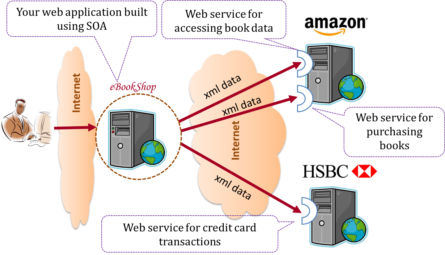
The service-oriented architecture (SOA) style builds applications by combining functionalities packaged as programmatically accessible services. SOA aims to achieve interoperability between distributed services, which may not even be implemented using the same programming language. A common way to implement SOA is through the use of XML web services where the web is used as the medium for the services to interact, and XML is used as the language of communication between service providers and service users.
Suppose that Amazon.com provides a web service for customers to browse and buy merchandise, while HSBC provides a web service for merchants to charge HSBC credit cards. Using these web services, an ‘eBookShop’ web application can be developed that allows HSBC customers to buy merchandise from Amazon and pay for them using HSBC credit cards. Because both Amazon and HSBC services follow the SOA architecture, their web services can be reused by the web application, even if all three systems use different programming platforms.
Design → Architecture → Styles → Using styles
Can explain how architectural styles are combined
Most applications use a mix of these architectural styles.
An application can use a client-server architecture where the server component comprises several layers, i.e. it uses the n-tier architecture.
Exercises
Comment on how to use architecture styles in Minesweeper.
Assume you are designing a multiplayer version of the Minesweeper game where any number of players can play the same Minefield. Players use their own PCs to play the game. A player scores by deducing a cell correctly before any of the other players do. Once a cell is correctly deduced, it appears as either marked or cleared for all players.
Comment on how each of the following architectural styles could be potentially useful when designing the architecture for this game.
- Client-server
- Transaction-processing
- SOA (Service Oriented Architecture)
- multi-layer (n-tier)
- Client-server – Clients can be the game UI running on player PCs. The server can be the game logic running on one machine.
- Transaction-processing – Each player action can be packaged as transactions (by the client component running on the player PC) and sent to the server. Server processes them in the order they are received.
- SOA – The game can access a remote web service for things such as getting new puzzles, validating puzzles, charging players subscription fees, etc.
- Multi-layer – The server component can have two layers: the logic layer and the storage layer.

Design → Architecture → Styles → More styles
Can name several other architecture styles
Other well-known architectural styles include the pipes-and-filters architecture, the broker architecture, the peer-to-peer architecture, and the message-oriented architecture.
Resources
-
Pipes and Filters pattern -- an article from Microsoft about the pipes and filters architectural style
-
Broker pattern -- Wikipedia article on the broker architectural style
-
Peer-to-peer pattern -- Wikipedia article on the P2P architectural style
-
Message-driven processing -- a post by Margaret Rouse
Follow up notes for the item(s) above:
As with design patterns, we covered only a few architecture styles. Although you didn't have to design an architecture in the tP, knowing the existence of these styles might come in handy in your future projects.
Guidance for the item(s) below:
Quality Assurance → Test Case Design → Combining Test Inputs → Why
Can explain the need for strategies to combine test inputs
An SUT can take multiple inputs. You can select values for each input (using equivalence partitioning, boundary value analysis, or some other technique).
An SUT that takes multiple inputs and some values chosen for each input:
- Method to test:
calculateGrade(participation, projectGrade, isAbsent, examScore) - Values to test:
Input Valid values to test Invalid values to test participation 0, 1, 19, 20 21, 22 projectGrade A, B, C, D, F isAbsent true, false examScore 0, 1, 69, 70, 71, 72
Testing all possible combinations is effective but not efficient. If you test all possible combinations for the above example, you need to test 6x5x2x6=360 cases. Doing so has a higher chance of discovering bugs (i.e. effective) but the number of test cases will be too high (i.e. not efficient). Therefore, you need smarter ways to combine test inputs that are both effective and efficient.
Quality Assurance → Test Case Design → Combining Test Inputs → Test input combination strategies
Can explain some basic test input combination strategies
Given below are some basic strategies for generating a set of test cases by combining multiple test inputs.
Let's assume the SUT has the following three inputs and you have selected the given values for testing:
SUT: foo(char p1, int p2, boolean p3)
Values to test:
| Input | Values |
|---|---|
| p1 | a, b, c |
| p2 | 1, 2, 3 |
| p3 | T, F |
The all combinations strategy generates test cases for each unique combination of test inputs.
This strategy generates 3x3x2=18 test cases.
| Test Case | p1 | p2 | p3 |
|---|---|---|---|
| 1 | a | 1 | T |
| 2 | a | 1 | F |
| 3 | a | 2 | T |
| ... | ... | ... | ... |
| 18 | c | 3 | F |
The at least once strategy includes each test input at least once.
This strategy generates 3 test cases.
| Test Case | p1 | p2 | p3 |
|---|---|---|---|
| 1 | a | 1 | T |
| 2 | b | 2 | F |
| 3 | c | 3 | VV/IV |
VV/IV = Any Valid Value / Any Invalid Value
The all pairs strategy creates test cases so that for any given pair of inputs, all combinations between them are tested. It is based on the observation that a bug is rarely the result of more than two interacting factors. The resulting number of test cases is lower than the all combinations strategy, but higher than the at least once approach.
This strategy generates 9 test cases:
See steps
Let's first consider inputs p1 and p2:
| Input | Values |
|---|---|
| p1 | a, b, c |
| p2 | 1, 2, 3 |
These values can generate (a,1)(a,2)(a,3)(b,1)(b,2),...3x3=9 combinations, and the test cases should cover all of them.
Next, let's consider p1 and p3.
| Input | Values |
|---|---|
| p1 | a, b, c |
| p3 | T, F |
These values can generate (a,T)(a,F)(b,T)(b,F),...3x2=6 combinations, and the test cases should cover all of them.
Similarly, inputs p2 and p3 generate another 6 combinations.
The 9 test cases given below cover all the above 9+6+6 combinations.
| Test Case | p1 | p2 | p3 |
|---|---|---|---|
| 1 | a | 1 | T |
| 2 | a | 2 | T |
| 3 | a | 3 | F |
| 4 | b | 1 | F |
| 5 | b | 2 | T |
| 6 | b | 3 | F |
| 7 | c | 1 | T |
| 8 | c | 2 | F |
| 9 | c | 3 | T |
A variation of this strategy is to test all pairs of inputs but only for inputs that could influence each other.
Testing all pairs between p1 and p3 only while ensuring all p2 values are tested at least once:
| Test Case | p1 | p2 | p3 |
|---|---|---|---|
| 1 | a | 1 | T |
| 2 | a | 2 | F |
| 3 | b | 3 | T |
| 4 | b | VV/IV | F |
| 5 | c | VV/IV | T |
| 6 | c | VV/IV | F |
The random strategy generates test cases using one of the other strategies and then picks a subset randomly (presumably because the original set of test cases is too big).
There are other strategies that can be used too.
Quality Assurance → Test Case Design → Combining Test Inputs → Heuristic: Each valid input at least once in a positive test case
Can apply heuristic ‘each valid input at least once in a positive test case’
Consider the following scenario.
SUT: printLabel(String fruitName, int unitPrice)
Selected values for fruitName (invalid values are underlined):
| Values | Explanation |
|---|---|
| Apple | Label format is round |
| Banana | Label format is oval |
| Cherry | Label format is square |
| Dog | Not a valid fruit |
Selected values for unitPrice:
| Values | Explanation |
|---|---|
| 1 | Only one digit |
| 20 | Two digits |
| 0 | Invalid because 0 is not a valid price |
| -1 | Invalid because negative prices are not allowed |
Suppose these are the test cases being considered.
| Case | fruitName | unitPrice | Expected |
|---|---|---|---|
| 1 | Apple | 1 | Print label |
| 2 | Banana | 20 | Print label |
| 3 | Cherry | 0 | Error message “invalid price” |
| 4 | Dog | -1 | Error message “invalid fruit" |
It looks like the test cases were created using the at least once strategy. After running these tests, can you confirm that the square-format label printing is done correctly?
- Answer: No.
- Reason:
Cherry-- the only input that can produce a square-format label -- is in a negative test case which produces an error message instead of a label. If there is a bug in the code that prints labels in square-format, these tests cases will not trigger that bug.
In this case, a useful heuristic to apply is each valid input must appear at least once in a positive test case. Cherry is a valid test input and you must ensure that it appears at least once in a positive test case. Here are the updated test cases after applying that heuristic.
| Case | fruitName | unitPrice | Expected |
|---|---|---|---|
| 1 | Apple | 1 | Print round label |
| 2 | Banana | 20 | Print oval label |
| 2.1 | Cherry | VV | Print square label |
| 3 | VV | 0 | Error message “invalid price” |
| 4 | Dog | -1 | Error message “invalid fruit" |
VV/IV = Any Invalid or Valid Value VV = Any Valid Value
Quality Assurance → Test Case Design → Combining Test Inputs → Heuristic: No more than one invalid input in a test case
Quality Assurance → Test Case Design → Combining Test Inputs → Heuristic: Each Valid Input at Least Once in a Positive Test Case
Can apply heuristic ‘no more than one invalid input in a test case’
Consider the test cases designed in [Heuristic: each valid input at least once in a positive test case].
| Case | fruitName | unitPrice | Expected |
|---|---|---|---|
| 1 | Apple | 1 | Print round label |
| 2 | Banana | 20 | Print oval label |
| 2.1 | Cherry | VV | Print square label |
| 3 | VV | 0 | Error message “invalid price” |
| 4 | Dog | -1 | Error message “invalid fruit" |
VV/IV = Any Invalid or Valid Value VV = Any Valid Value
After running these test cases, can you be sure that the error message “invalid price” is shown for negative prices?
- Answer: No.
- Reason:
-1-- the only input that is a negative price -– is in a test case that produces the error message “invalid fruit”.
In this case, a useful heuristic to apply is no more than one invalid input in a test case. After applying that, you get the following test cases.
| Case | fruitName | unitPrice | Expected |
|---|---|---|---|
| 1 | Apple | 1 | Print round label |
| 2 | Banana | 20 | Print oval label |
| 2.1 | Cherry | VV | Print square label |
| 3 | VV | 0 | Error message “invalid price” |
| 4 | VV | -1 | Error message “invalid price" |
| 4.1 | Dog | VV | Error message “invalid fruit" |
VV/IV = Any Invalid or Valid Value VV = Any Valid Value
Exercises
Can define test cases precisely
Applying the heuristics covered so far, we can determine the precise number of test cases required to test any given SUT effectively.
False
Explanation: These heuristics are, well, heuristics only. They will help you to make better decisions about test case design. However, they are speculative in nature (especially, when testing in black-box fashion) and cannot give you the precise number of test cases.
Quality Assurance → Test Case Design → Combining Test Inputs → Mix
Can apply multiple test input combination techniques together
Consider the calculateGrade scenario given below:
- SUT:
calculateGrade(participation, projectGrade, isAbsent, examScore) - Values to test: invalid values are underlined
- participation: 0, 1, 19, 20, 21, 22
- projectGrade: A, B, C, D, F
- isAbsent: true, false
- examScore: 0, 1, 69, 70, 71, 72
To get the first cut of test cases, let’s apply the at least once strategy.
Test cases for calculateGrade V1
| Case No. | participation | projectGrade | isAbsent | examScore | Expected |
|---|---|---|---|---|---|
| 1 | 0 | A | true | 0 | ... |
| 2 | 1 | B | false | 1 | ... |
| 3 | 19 | C | VV/IV | 69 | ... |
| 4 | 20 | D | VV/IV | 70 | ... |
| 5 | 21 | F | VV/IV | 71 | Err Msg |
| 6 | 22 | VV/IV | VV/IV | 72 | Err Msg |
VV/IV = Any Valid or Invalid Value, Err Msg = Error Message
Next, let’s apply the each valid input at least once in a positive test case heuristic. Test case 5 has a valid value for projectGrade=F that doesn't appear in any other positive test case. Let's replace test case 5 with 5.1 and 5.2 to rectify that.
Test cases for calculateGrade V2
| Case No. | participation | projectGrade | isAbsent | examScore | Expected |
|---|---|---|---|---|---|
| 1 | 0 | A | true | 0 | ... |
| 2 | 1 | B | false | 1 | ... |
| 3 | 19 | C | VV | 69 | ... |
| 4 | 20 | D | VV | 70 | ... |
| 5.1 | VV | F | VV | VV | ... |
| 5.2 | 21 | VV/IV | VV/IV | 71 | Err Msg |
| 6 | 22 | VV/IV | VV/IV | 72 | Err Msg |
VV = Any Valid Value VV/IV = Any Valid or Invalid Value
Next, you have to apply the no more than one invalid input in a test case heuristic. Test cases 5.2 and 6 don't follow that heuristic. Let's rectify the situation as follows:
Test cases for calculateGrade V3
| Case No. | participation | projectGrade | isAbsent | examScore | Expected |
|---|---|---|---|---|---|
| 1 | 0 | A | true | 0 | ... |
| 2 | 1 | B | false | 1 | ... |
| 3 | 19 | C | VV | 69 | ... |
| 4 | 20 | D | VV | 70 | ... |
| 5.1 | VV | F | VV | VV | ... |
| 5.2 | 21 | VV | VV | VV | Err Msg |
| 5.3 | 22 | VV | VV | VV | Err Msg |
| 6.1 | VV | VV | VV | 71 | Err Msg |
| 6.2 | VV | VV | VV | 72 | Err Msg |
Next, you can assume that there is a dependency between the inputs examScore and isAbsent such that an absent student can only have examScore=0. To cater for the hidden invalid case arising from this, you can add a new test case where isAbsent=true and examScore!=0. In addition, test cases 3-6.2 should have isAbsent=false so that the input remains valid.
Test cases for calculateGrade V4
| Case No. | participation | projectGrade | isAbsent | examScore | Expected |
|---|---|---|---|---|---|
| 1 | 0 | A | true | 0 | ... |
| 2 | 1 | B | false | 1 | ... |
| 3 | 19 | C | false | 69 | ... |
| 4 | 20 | D | false | 70 | ... |
| 5.1 | VV | F | false | VV | ... |
| 5.2 | 21 | VV | false | VV | Err Msg |
| 5.3 | 22 | VV | false | VV | Err Msg |
| 6.1 | VV | VV | false | 71 | Err Msg |
| 6.2 | VV | VV | false | 72 | Err Msg |
| 7 | VV | VV | true | !=0 | Err Msg |
Exercises
Statements about test input combinations
Which one of these contradicts the heuristics recommended when creating test cases with multiple inputs?
a
Explanation: If you test all invalid test inputs together, you will not know if each of the invalid inputs is handled correctly by the SUT. This is because most SUTs return an error message upon encountering the first invalid input.
Combine test inputs for the consume method
Apply heuristics for combining multiple test inputs to improve the E&E of the following test cases, assuming all 6 values in the table need to be tested. Underlines indicate invalid values. Point out where the heuristics are contradicted and how to improve the test cases.
SUT: consume(food, drink)
| Test case | food | drink |
|---|---|---|
| TC1 | bread | water |
| TC2 | rice | lava |
| TC3 | rock | acid |
Guidance for the item(s) below:
Testing is the first thing that comes to mind when you hear 'Quality Assurance' but there are other QA techniques that can complement testing. Let's first take a step back and take a look at QA in general, followed by a look at some other QA techniques.
Quality Assurance → Quality Assurance → Introduction → What
Can explain software quality assurance
Software Quality Assurance (QA) is the process of ensuring that the software being built has the required levels of quality.
While testing is the most common activity used in QA, there are other complementary techniques such as static analysis, code reviews, and formal verification.
Quality Assurance → Quality Assurance → Introduction → Validation versus verification
Can explain validation and verification
Quality Assurance = Validation + Verification
QA involves checking two aspects:
- Validation: are you building the right system i.e., are the requirements correct?
- Verification: are you building the system right i.e., are the requirements implemented correctly?
Whether something belongs under validation or verification is not that important. What is more important is that both are done, instead of limiting to only verification (i.e., remember that the requirements can be wrong too).
Exercises
Statements about validation and verification
Choose the correct statements about validation and verification.
- a. Validation: Are we building the right product?, Verification: Are we building the product right?
- b. It is very important to clearly distinguish between validation and verification.
- c. The important thing about validation and verification is to remember to pay adequate attention to both.
- d. Developer-testing is more about verification than validation.
- e. QA covers both validation and verification.
- f. A system crash is more likely to be a verification failure than a validation failure.
(a)(b)(c)(d)(e)(f)
Explanation:
Whether something belongs under validation or verification is not that important. What is more important is that we do both.
Developer testing is more about finding bugs in the code, rather than bugs in the requirements.
In QA, system testing is more about verification (does the system follow the specification?) and acceptance testing is more about validation (does the system solve the user’s problem?).
A system crash is more likely to be a bug in the code, not in the requirements.
Quality Assurance → Quality Assurance → Formal Verification → What
Can explain formal verification
Formal verification uses mathematical techniques to prove the correctness of a program.
An introduction to Formal Methods
by Eric Hehner
Advantages:
- Formal verification can be used to prove the absence of errors. In contrast, testing can only prove the presence of errors, not their absence.
Disadvantages:
- It only proves the compliance with the specification, but not the actual utility of the software.
- It requires highly specialized notations and knowledge which makes it an expensive technique to administer. Therefore, formal verifications are more commonly used in safety-critical software such as flight control systems.
Exercises
Absence of errors
Testing cannot prove the absence of errors. It can only prove the presence of errors. However, formal methods can prove the absence of errors.
True
Explanation: While using formal methods is more expensive than testing, it can indeed prove the correctness of a piece of software conclusively, in certain contexts. Getting such proof via testing requires exhaustive testing, which is not practical to do in most cases.
Guidance for the item(s) below:
Do you know the difference between a library and a framework?
Programmers often reuse code in various ways. The next few topics aim to clarify the difference between several forms reusable software comes in.
APIs
Implementation → Reuse → Introduction → What
Can explain software reuse
Reuse is a major theme in software engineering practices. By reusing tried-and-tested components, the robustness of a new software system can be enhanced while reducing the manpower and time requirement. Reusable components come in many forms; it can be reusing a piece of code, a subsystem, or a whole software.
Implementation → Reuse → Introduction → When
Can explain the costs and benefits of reuse
While you may be tempted to use many libraries/frameworks/platforms that seem to crop up on a regular basis and promise to bring great benefits, note that there are costs associated with reuse. Here are some:
- The reused code may be an overkill (think using a sledgehammer to crack a nut), increasing the size of, and/or degrading the performance of, your software.
- The reused software may not be mature/stable enough to be used in an important product. That means the software can change drastically and rapidly, possibly in ways that break your software.
- Non-mature software has the risk of dying off as fast as they emerged, leaving you with a dependency that is no longer maintained.
- The license of the reused software (or its dependencies) restrict how you can use/develop your software.
- The reused software might have bugs, missing features, or security vulnerabilities that are important to your product, but not so important to the maintainers of that software, which means those flaws will not get fixed as fast as you need them to.
- Malicious code can sneak into your product via compromised dependencies.
Exercises
Using a cool UI framework
One of your teammates is proposing to use a recently-released “cool” UI framework for your class project. List the pros and cons of this idea.
Pros
- The potential to create a much better product by reusing the framework.
- Learning a new framework is good for future job prospects.
Cons
- Learning curve may be steep.
- May not be stable (as it was recently released).
- May not allow you to do exactly what you want. While frameworks allow customization, such customization can be limited.
- Performance penalties.
- Might interfere with the learning objectives of the module.
Note that having more cons does not mean you should not use this framework. Further investigation is required before you can make a final decision.
Libraries
Implementation → Reuse → Libraries → What
Can explain libraries
A library is a collection of modular code that is general and can be used by other programs.
Java classes you get with the JDK (such as String, ArrayList, HashMap, etc.) are library classes that are provided in the default Java distribution.
Natty is a Java library that can be used for parsing strings that represent dates e.g. The 31st of April in the year 2008
built-in modules you get with Python (such as csv, random, sys, etc.) are libraries that are provided in the default Python distribution. Classes such as list, str, dict are built-in library classes that you get with Python.
Colorama is a Python library that can be used for colorizing text in a CLI.
Implementation → Reuse → Libraries → How
Can make use of a library
These are the typical steps required to use a library:
- Read the documentation to confirm that its functionality fits your needs.
- Check the license to confirm that it allows reuse in the way you plan to reuse it. For example, some libraries might allow non-commercial use only.
- Download the library and make it accessible to your project. Alternatively, you can configure your e.g. Gradle (for Java) and Pipenv (for Python)dependency management tool to do it for you.
- Call the library API from your code where you need to use the library's functionality.
Implementation → Reuse → APIs → What
Can explain APIs
An Application Programming Interface (API) specifies the interface through which other programs can interact with a software component. It is a contract between the component and its clients.
A class has an API (e.g., API of the Java String class, API of the Python str class) which is a collection of public methods that you can invoke to make use of the class.
The GitHub API is a collection of web request formats that the GitHub server accepts and their corresponding responses. You can write a program that interacts with GitHub through that API.
When developing large systems, if you define the API of each component early, the development team can develop the components in parallel because the future behavior of the other components are now more predictable.
Exercises
Statements about APIs
Choose the correct statements.
- a. A software component can have an API.
- b. Any method of a class is part of its API.
- c. Private methods of a class are not part of its API.
- d. The API forms the contract between the component developer and the component user.
- e. Sequence diagrams can be used to show how components interact with each other via APIs.
(a) (c) (d) (e)
Explanation: (b) is incorrect because private methods cannot be a part of the API.
True or False?
Defining component APIs early is useful for developing components in parallel.
True
Explanation: Yes, once you know the precise behavior expected of each component, you can start developing them in parallel.
Frameworks
Implementation → Reuse → Frameworks → What
Can explain frameworks
The overall structure and execution flow of a specific category of software systems can be very similar. The similarity is an opportunity to reuse at a high scale.
Running example:
IDEs for different programming languages are similar in how they support editing code, organizing project files, debugging, etc.
A software framework is a reusable implementation of a software (or part thereof) providing generic functionality that can be selectively customized to produce a specific application.
Running example:
Eclipse is an IDE framework that can be used to create IDEs for different programming languages.
Some frameworks provide a complete implementation of a default behavior which makes them immediately usable.
Running example:
Eclipse is a fully functional Java IDE out-of-the-box.
A framework facilitates the adaptation and customization of some desired functionality.
Running example:
The Eclipse plugin system can be used to create an IDE for different programming languages while reusing most of the existing IDE features of Eclipse.
E.g. https://marketplace.eclipse.org/content/pydev-python-ide-eclipse
Some frameworks cover only a specific component or an aspect.
JavaFX is a framework for creating Java GUIs. Tkinter is a GUI framework for Python.
More examples of frameworks
- Frameworks for web-based applications: Drupal (PHP), Django (Python), Ruby on Rails (Ruby), Spring (Java)
- Frameworks for testing: JUnit (Java), unittest (Python), Jest (JavaScript)
Implementation → Reuse → Frameworks → Frameworks versus libraries
Can differentiate between frameworks and libraries
Although both frameworks and libraries are reuse mechanisms, there are notable differences:
-
Libraries are meant to be used ‘as is’ while frameworks are meant to be customized/extended. e.g., writing plugins for Eclipse so that it can be used as an IDE for different languages (C++, PHP, etc.), adding modules and themes to Drupal, and adding test cases to JUnit.
-
Your code calls the library code while the framework code calls your code. Frameworks use a technique called inversion of control, aka the “Hollywood principle” (i.e. don’t call us, we’ll call you!). That is, you write code that will be called by the framework, e.g. writing test methods that will be called by the JUnit framework. In the case of libraries, your code calls libraries.
Exercises
Statement about software frameworks
Choose the correct statements about software frameworks.
- a. They follow the Hollywood principle, otherwise known as ‘inversion of control’.
- b. They come with full or partial implementations.
- c. They are more concrete than patterns or principles.
- d. They are often configurable.
- e. They are reuse mechanisms.
- f. They are similar to reusable libraries but bigger.
(a)(b)(c)(d)(e)(f)
Explanation: While both libraries and frameworks are reuse mechanisms, and both are more concrete than principles and patterns, libraries differ from frameworks in some key ways. One of them is the ‘inversion of control’ used by frameworks but not libraries. Furthermore, frameworks do not have to be bigger than libraries all the time.
Which are frameworks?
Which of these are frameworks?
- a. JUnit
- b. Eclipse
- c. Drupal
- d. Ruby on Rails
(a)(b)(c)(d)
Explanation: These are all frameworks.
Platforms
Implementation → Reuse → Platforms → What
Can explain platforms
A platform provides a runtime environment for applications. A platform is often bundled with various libraries, tools, frameworks, and technologies in addition to a runtime environment but the defining characteristic of a software platform is the presence of a runtime environment.
Technically, an operating system can be called a platform. For example, Windows PC is a platform for desktop applications while iOS is a platform for mobile applications.
Two well-known examples of platforms are JavaEE and .NET, both of which sit above the operating systems layer, and are used to develop enterprise applications. Infrastructure services such as connection pooling, load balancing, remote code execution, transaction management, authentication, security, messaging etc. are done similarly in most enterprise applications. Both JavaEE and .NET provide these services to applications in a customizable way without developers having to implement them from scratch every time.
- JavaEE (Java Enterprise Edition) is both a framework and a platform for writing enterprise applications. The runtime used by JavaEE applications is the JVM (Java Virtual Machine) that can run on different Operating Systems.
- .NET is a similar platform and framework. Its runtime is called CLR (Common Language Runtime) and it is usually used on Windows machines.
Enterprise application: ‘enterprise applications’ refer to software applications used by organizations and therefore have to meet much higher demands (such as in scalability, security, performance, and robustness) than software meant for individual use.
Guidance for the item(s) below:
While not examinable, the next few sections explain some basic cloud computing concepts that are relevant to software engineers.
Implementation → Reuse → Cloud Computing → What
Can explain cloud computing
Cloud computing is the delivery of computing as a service over the network, rather than a product running on a local machine. This means the actual hardware and software is located at a remote location, typically, at a large server farm, while users access them over the network. Maintenance of the hardware and software is managed by the cloud provider while users typically pay for only the amount of services they use. This model is similar to the consumption of electricity; the power company manages the power plant, while the consumers pay them only for the electricity used. The cloud computing model optimizes hardware and software utilization and reduces the cost to consumers. Furthermore, users can scale up/down their utilization at will without having to upgrade their hardware and software. The traditional non-cloud model of computing is similar to everyone buying their own generators to create electricity for their own use.
Implementation → Reuse → Cloud Computing → Iaas, PaaS, and SaaS
Can distinguish between IaaS, PaaS, and SaaS
source: https://commons.wikimedia.org
Cloud computing can deliver computing services at three levels:
-
Infrastructure as a service (IaaS) delivers computer infrastructure as a service. For example, a user can deploy virtual servers on the cloud instead of buying physical hardware and installing server software on them. Another example would be a customer using storage space on the cloud for off-site storage of data. Rackspace is an example of an IaaS cloud provider. Amazon Elastic Compute Cloud (Amazon EC2) is another one.
-
Platform as a service (PaaS) provides a platform on which developers can build applications. Developers do not have to worry about infrastructure issues such as deploying servers or load balancing as is required when using IaaS. Those aspects are automatically taken care of by the platform. The price to pay is reduced flexibility; applications written on PaaS are limited to facilities provided by the platform. A PaaS example is the Google App Engine where developers can build applications using Java, Python, PHP, or Go whereas Amazon EC2 allows users to deploy applications written in any language on their virtual servers.
-
Software as a service (SaaS) allows applications to be accessed over the network instead of installing them on a local machine. For example, Google Docs is a SaaS word processing software, while Microsoft Word is a traditional word processing software.
Exercises
Google Calendar is in which category?
Google Calendar belongs to which category of cloud computing services?
(c)
Explanation: It is a software as a service. Instead of installing a calendar software on your desktop, you can use the Google Calendar software that lives ‘on the cloud’.
Guidance for the item(s) below:
To complete the picture about UML, given below are a peek into the other types of UML diagrams.
Design → Modelling → Modelling Behaviors Communication diagrams
Can explain communication diagrams
Communication diagrams are like sequence diagrams but emphasize the data links between the various participants in the interaction rather than the sequence of interactions.
An example:

Adapted from: UML Distilled by Martin Fowler
Design → Modelling → Modelling Behaviors State machine diagrams
Can explain state machine diagrams
A State Machine Diagram models state-dependent behavior.
Consider how a CD player responds when the “eject CD” button is pushed:
- If the CD tray is already open, it does nothing.
- If the CD tray is already in the process of opening (opened half-way), it continues to open the CD tray.
- If the CD tray is closed and the CD is being played, it stops playing and opens the CD tray.
- If the CD tray is closed and CD is not being played, it simply opens the CD tray.
- If the CD tray is already in the process of closing (closed half-way), it waits until the CD tray is fully closed and opens it immediately afterwards.
What this means is that the CD player’s response to pushing the “eject CD” button depends on what it was doing at the time of the event. More generally, the CD player’s response to the event received depends on its internal state. Such a behavior is called a state-dependent behavior.
Often, state-dependent behavior displayed by an object in a system is simple enough that it needs no extra attention; such a behavior can be as simple as a conditional behavior like if x > y, then x = x - y.
Occasionally, objects may exhibit state-dependent behavior that is complex enough such that it needs to be captured in a separate model. Such state-dependent behavior can be modeled using UML state machine diagrams (SMD for short, sometimes also called ‘state charts’, ‘state diagrams’ or ‘state machines’).
Occasionally, objects may exhibit state-dependent behavior that is complex enough such that it needs to be captured into a separate model. Such state-dependent behavior can be modelled using UML state machine diagrams (SMD for short, sometimes also called ‘state charts’, ‘state diagrams’ or ‘state machines’).
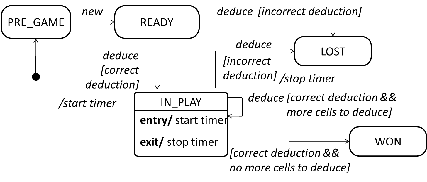
An SMD views the life-cycle of an object as consisting of a finite number of states where each state displays a unique behavior pattern. SMDs capture information such as the states an object can be in during its lifetime, how the object responds to various events while in each state, and how the object transits from one state to another. In contrast to sequence diagrams that capture object behavior one scenario at a time, SMDs capture the object’s behavior over its full life-cycle.
An SMD for the Minesweeper game.
Design → Modelling → Modelling Structure → Deployment diagrams
Can explain deployment diagrams
A deployment diagram shows a system's physical layout, revealing which pieces of software run on which pieces of hardware.
An example deployment diagram:

Design → Modelling → Modelling Structure → Component diagrams
Can explain component diagrams
A component diagram is used to show how a system is divided into components and how they are connected to each other through interfaces.
An example component diagram:

Design → Modelling → Modelling Structure → Package diagrams
Can explain package diagrams
A package diagram shows packages and their dependencies. A package is a grouping construct for grouping UML elements (classes, use cases, etc.).
Here is an example package diagram:
Design → Modelling → Modelling Structure → Composite structure diagrams
Can explain composite structure diagrams
A composite structure diagram hierarchically decomposes a class into its internal structure.
Here is an example composite structure diagram:

Design → Modelling → Modelling Behaviors Timing diagrams
Can explain timing diagrams
A timing diagram focuses on timing constraints.
Here is an example timing diagram:

Adapted from: UML Distilled by Martin Fowler
Design → Modelling → Modelling Behaviors Interaction overview diagrams
Can explain interaction overview diagrams
Interaction overview diagrams are a combination of activity diagrams and sequence diagrams.
An example:

source: https://commons.wikimedia.org
