Team Project (tP):
Week 6 [Fri, Sep 11th] - Topics
Detailed Table of Contents
- [W6.1] Modeling: Sequence Diagrams
- [W6.2] Architecture Diagrams
- [W6.3] IDEs: Intermediate Features
- [W6.4] Logging
Guidance for the item(s) below:
The next UML model we'll be learning is sequence diagrams. As before, focus on learning how to interpret these diagrams as you'll need to interpret some sequence diagrams in tP documentation pretty soon. Drawing sequence diagrams will be covered in a future week.
Design → Modelling → Modelling Behaviors Sequence diagrams - basic
Can draw basic sequence diagrams
UML Sequence Diagrams → Introduction UML/SequenceDiagrams
UML Sequence Diagrams → Basic Notation UML/SD/Basic
UML Sequence Diagrams → Loops UML/SD/Loops UML Sequence Diagrams → Object Creation UML/SD/Creation
UML Sequence Diagrams → Minimal Notation UML/SD/Minimal
Exercises
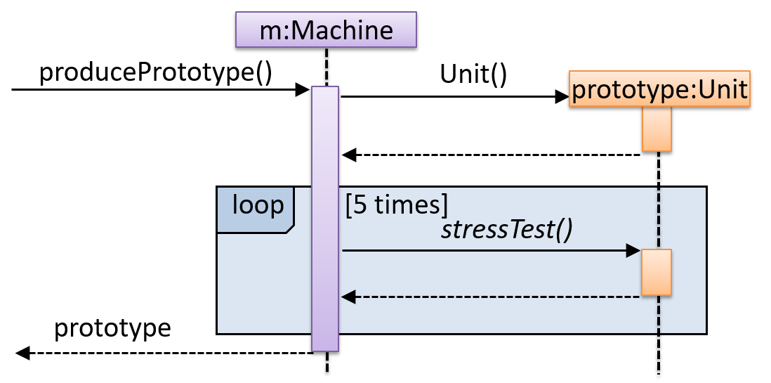
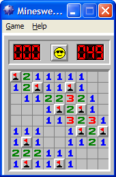
Explain Sequence Diagram about Machine
Explain in your own words the interactions illustrated by this Sequence Diagram:
Draw a Sequence Diagram for the code (PersonList, Person, Tag)
Consider the code below:
class Person {
    Tag tag;
    String name;

    Person(String personName, String tagName) {
        name = personName;
        tag = new Tag(tagName);
    }
}
class Tag {
    Tag(String value) {
        // ...
    }
}

class PersonList {
    void addPerson(Person p) {
        // ...
    }
}
Draw a sequence diagram to illustrate the object interactions that happen in the code snippet below:
PersonList personList = new PersonList();
while (hasRoom) {
    Person p = new Person("Adam", "friend");
    personList.addPerson(p);
}
Find notation errors in Sequence Diagram
Find notation mistakes in the sequence diagram below:
Design → Modelling → Modelling Behaviors Sequence diagrams - intermediate
Can draw intermediate-level sequence diagrams
UML Sequence Diagrams → Object Deletion UML/SD/Deletion UML Sequence Diagrams → Self-Invocation UML/SD/Self-Invocation UML Sequence Diagrams → Alternative Paths UML/SD/Alternative UML Sequence Diagrams → Optional Paths UML/SD/Optional
UML Sequence Diagrams → Calls to Static Methods
UML/SD/StaticMethods
Method calls to static (i.e., class-level) methods are received by the class itself, not an instance of that class. You can use <<class>> to show that a participant is the class itself.
In this example, m calls the static method Person.getMaxAge() and also the setAge() method of a Person object p.
Here is the Person class, for reference:
Exercises
What’s going on here?
What’s going on here?
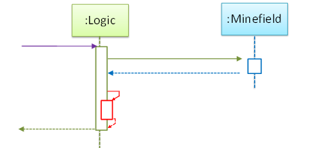
- a.
Logicobject is executing a parallel thread. - b.
Logicobject is executing a loop. - c.
Logicobject is creating anotherLogicinstance. - d. One of
Logicobject’s methods is calling another of its methods. - e.
Minefieldobject is calling a method ofLogic.
(d)
Explain Sequence Diagram (ParserFactory)
Explain the interactions depicted in this sequence diagram.
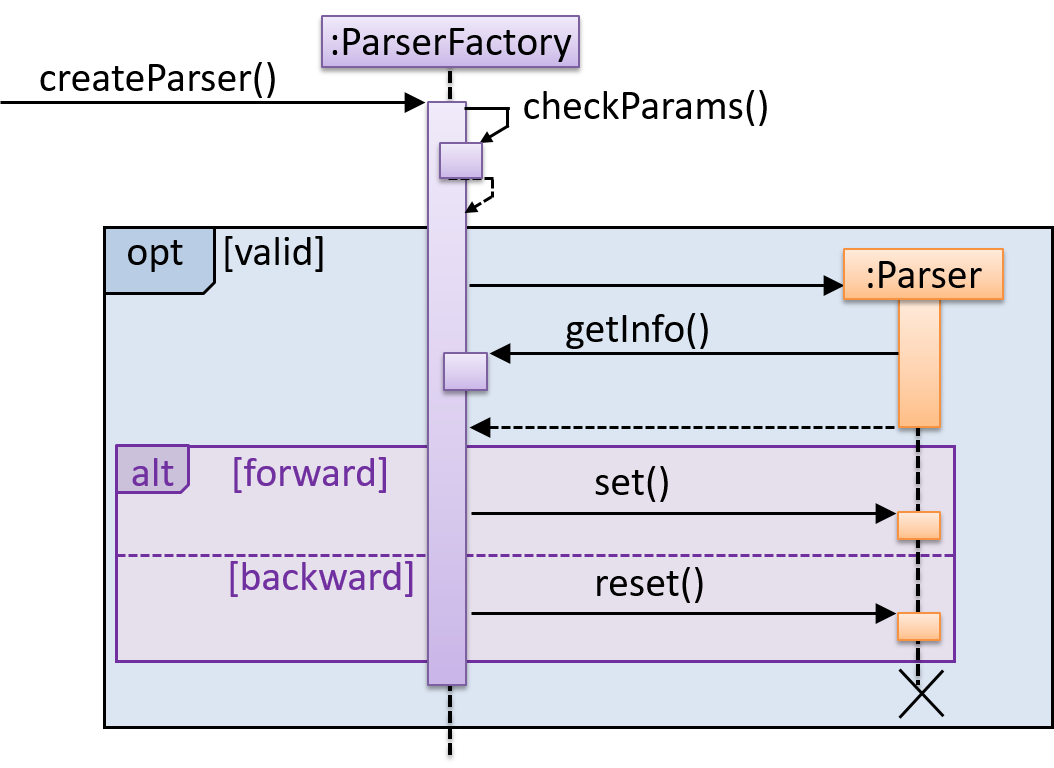
First, the createParser() method of an existing ParserFactory object is called. Then, ...
Draw Sequence Diagram for printing a quote
Draw a sequence diagram to represent this code snippet.
if (isFirstPage) {
    new Quote().print();
}
The Quote class:
class Quote {

    String q;

    Quote() {
        q = generate();
    }

    String generate() {
        // ...
    }

    void print() {
        System.out.println(q);
    }

}
- Show
new Quote().print();as two method calls. - As the created Quote object is not assigned to a variable, it can be considered as 'deleted' soon after its
print()method is called.
Tools → UML → Sequence Diagrams → Reference frames
Can interpret sequence diagrams with reference frames
UML uses ref frame to allow a segment of the interaction to be omitted and shown as a separate sequence diagram. Reference frames help you to break complicated sequence diagrams into multiple parts or simply to omit details you are not interested in showing.
Notation:
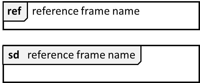
The details of the get minefield appearance interactions have been omitted from the diagram.
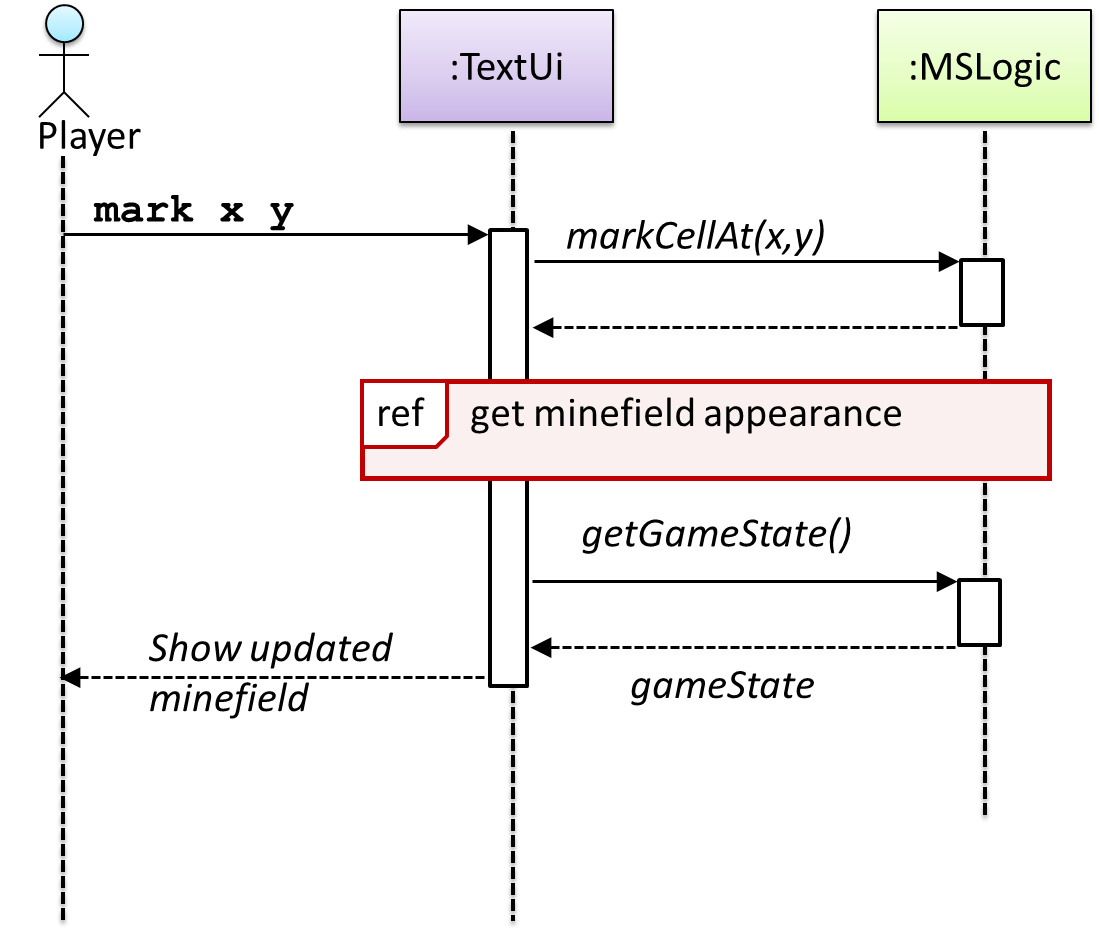
Those details are shown in a separate sequence diagram given below.

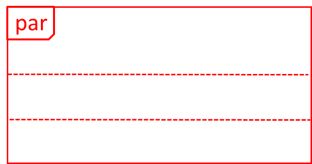
Tools → UML → Sequence Diagrams → Parallel paths
Can interpret sequence diagrams with parallel paths
UML uses par frames to indicate parallel paths.
Notation:
Logic is calling methods CloudServer#poll() and LocalServer#poll() in parallel.
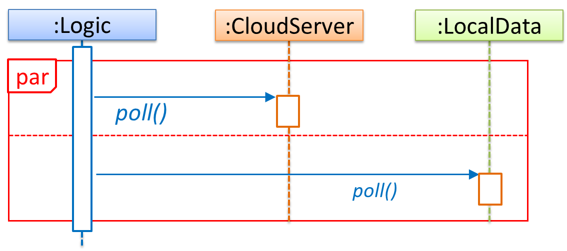
If you show parallel paths in a sequence diagram, the corresponding Java implementation is likely to be multi-threaded because a normal Java program cannot do multiple things at the same time.
Guidance for the item(s) below:
The tP developer guide also has something called an architecture diagram. Let's learn how to interpret them too (drawing them will be covered in a future week).
Design → Architecture → Introduction → What
Can explain Software Architecture
The software architecture of a program or computing system is the structure or structures of the system, which comprise software elements, the externally visible properties of those elements, and the relationships among them. Architecture is concerned with the public side of interfaces; private details of elements—details having to do solely with internal implementation—are not architectural. -- Software Architecture in Practice (2nd edition), Bass, Clements, and Kazman
The software architecture shows the overall organization of the system and can be viewed as a very high-level design. It usually consists of a set of interacting components that fit together to achieve the required functionality. It should be a simple and technically viable structure that is well-understood and agreed-upon by everyone in the development team, and it forms the basis for the implementation.
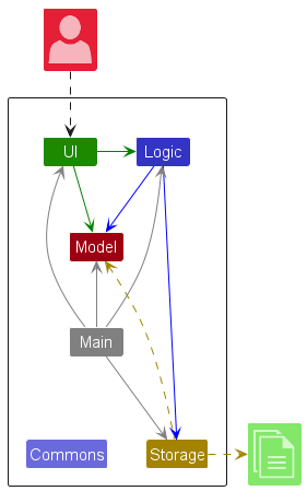
A possible architecture for a Minesweeper game:
 |
 |
Main components:
GUI: Graphical user interfaceTextUi: Textual user interfaceATD: An automated test driver used for testing the game logicLogic: Computation and logic of the gameStore: Storage and retrieval of game data (high scores etc.)
The architecture is typically designed by the software architect, who provides the technical vision of the system and makes high-level (i.e. architecture-level) technical decisions about the project.
Exercises
Statements about architecture
Choose the correct statement.
- a. The architecture of a system should be simple enough for all team members to understand it.
- b. The architecture is primarily a high-level design of the system.
- c. The architecture is usually decided by the project manager.
- d. The architecture can contain details private to a component.
(a)(b)
(c) Reason: Architecture is usually designed by the Architect.
(d) Reason:
... private details of elements—details having to do solely with internal implementation—are not architectural.
Design → Architecture → Architecture Diagrams → Reading
Design → Architecture → Introduction → What
Can interpret an architecture diagram
Architecture diagrams are free-form diagrams. There is no universally adopted standard notation for architecture diagrams. Any symbols that reasonably describe the architecture may be used.
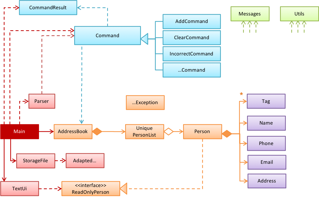
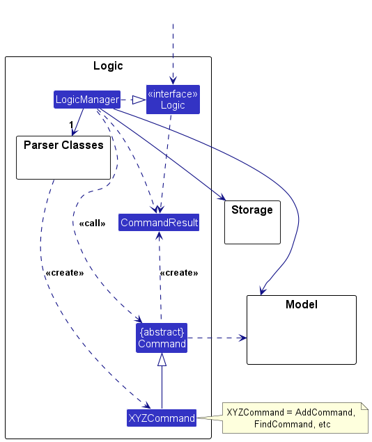
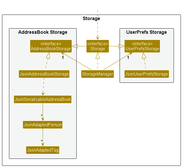
Some example architecture diagrams:


Guidance for the item(s) below:
As the tP is bigger than the iP, it's not possible to work with its entire design at the same time. The next topic explains a technique that can help when dealing with the design of a bigger system.
Design → Introduction → Multi-level design
Can explain multi-level design
In a smaller system, the design of the entire system can be shown in one place.
This class diagram of se-edu/addressbook-level2 depicts the design of the entire software.
The design of bigger systems needs to be done/shown at multiple levels.
This architecture diagram of se-edu/addressbook-level3 depicts the high-level design of the software.
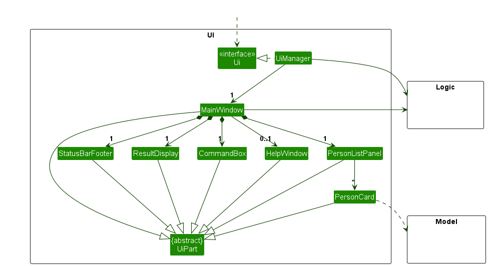
Here are examples of lower level designs of some components of the same software:
Guidance for the item(s) below:
It's time to push our IDEs to do more for us. The features given below can often make the IDEs worth the trouble.
Implementation → IDEs → Debugging → What
Can explain debugging
Debugging is the process of discovering defects in the program. Here are some approaches to debugging:
- Bad -- By inserting temporary print statements: This is an ad-hoc approach in which print statements are inserted in the program to print information relevant to debugging, such as variable values. e.g.
Exiting process() method, x is 5.347. This approach is not recommended due to these reasons:- Incurs extra effort when inserting and removing the print statements.
- These extraneous program modifications increase the risk of introducing errors into the program.
- These print statements, if not removed promptly after the debugging, may even appear unexpectedly in the production version.
- Bad -- By manually tracing through the code: Otherwise known as ‘eye-balling’, this approach doesn't have the cons of the previous approach, but it too is not recommended (other than as a 'quick try') due to these reasons:
- It is a difficult, time consuming, and error-prone technique.
- If you didn't spot the error while writing the code, you might not spot the error when reading the code either.
- Good -- Using a debugger: A debugger tool allows you to pause the execution, then step through the code one statement at a time while examining the internal state if necessary. Most IDEs come with an inbuilt debugger. This is the recommended approach for debugging.
Tools → IntelliJ IDEA → Debugging: Basic
Can step through a program using a debugger
This video (from LaunchCode) gives a pretty good explanation of how to use the IntelliJ IDEA debugger.
- IntelliJ IDEA Documentation: Debugging Basics - Can be used as a reference document when you want to recall how to use a debugging feature.
Tools → IntelliJ IDEA → Code navigation
Can navigate code effectively using IDE features
Some useful navigation shortcuts:
- Quickly locate a file by name.
- Go to the definition of a method from where it is used.
- Go back to the previous location.
- View the documentation of a method from where the method is being used, without navigating to the method itself.
- Find where a method/field is being used.
IntelliJ IDEA Code Navigation
Guidance for the item(s) below:
The tP uses logging as one of its error handing strategies. As you'll be reading tP code soon, let's make sure you can recognize logging code when you see them.
Implementation → Error Handling → Logging → What
Can explain logging
Logging is the deliberate recording of certain information during a program execution for future reference. Logs are typically written to a log file but it is also possible to log information in other ways e.g. into a database or a remote server.
Logging can be useful for troubleshooting problems. A good logging system records some system information regularly. When bad things happen to a system e.g. an unanticipated failure, their associated log files may provide indications of what went wrong and actions can then be taken to prevent it from happening again.
A log file is like the flight data recorderblack box of an airplane; they don't prevent problems but they can be helpful in understanding what went wrong after the fact.

source: https://commons.wikimedia.org
Exercises
Logging vs blackbox
Why is logging like having the 'black box' in an airplane?
(a)
Implementation → Error Handling → Logging → How
Can use logging
Most programming environments come with logging systems that allow sophisticated forms of logging. They have features such as the ability to enable and disable logging easily or to change the logging how much information to recordintensity.
This sample Java code uses Java’s default logging mechanism.
First, import the relevant Java package:
import java.util.logging.*;
Next, create a Logger:
private static Logger logger = Logger.getLogger("Foo");
Now, you can use the Logger object to log information. Note the use of a INFO, WARNING etc.logging level for each message. When running the code, the logging level can be set to WARNING so that log messages specified as having INFO level (which is a lower level than WARNING) will not be written to the log file at all.
// log a message at INFO level
logger.log(Level.INFO, "going to start processing");
// ...
processInput();
if (error) {
    // log a message at WARNING level
    logger.log(Level.WARNING, "processing error", ex);
}
// ...
logger.log(Level.INFO, "end of processing");
Resources
Tutorials:
- Java Logging API - Tutorial -- A tutorial by Lars Vogella
- Java Logging Tutorial -- An alternative tutorial by Jakob Jenkov
- A video tutorial by SimplyCoded:
Best Practices:
- 10 Tips for Proper Application Logging -- by Tomasz Nurkiewicz
- What each logging level means -- conventions recommended by Apache Project