This site is from a past semester! The current version will be here when the new semester starts.
CS2103/T 2020 Aug-Dec
  • Full Timeline
  • Week 1 [Mon, Aug 10th]
  • Week 2 [Fri, Aug 14th]
  • Week 3 [Fri, Aug 21st]
  • Week 4 [Fri, Aug 28th]
  • Week 5 [Fri, Sep 4th]
  • Week 6 [Fri, Sep 11th]
  • Week 7 [Fri, Sep 18th]
  • Week 8 [Fri, Oct 2nd]
  • Week 9 [Fri, Oct 9th]
  • Week 10 [Fri, Oct 16th]
  • Week 11 [Fri, Oct 23rd]
  • Week 12 [Fri, Oct 30th]
  • Week 13 [Fri, Nov 6th]
  • Textbook
  • Admin Info
  • Dashboards
  •  Individual Project (iP):
  • Individual Project Info
  • iP Upstream Repo
  • iP Showcase
  • iP Code Dashboard
  • iP Progress Dashboard

  •  Team Project (tP):
  • Team Project Info
  • Addressbook-level3
  • Team List
  • tP Code Dashboard
  • tP Progress Dashboard
  • Report Bugs
  • Forum
  • Gitter (Chat)
  • Instructors
  • Announcements
  • Files
  • Tutorial Schedule
  • Java Coding Standard
  • Git Conventions
  • Forum Activities Dashboard
  • Participation Dashboard
  • Week 9 [Fri, Oct 9th] - Topics

    • [W9.1] OO Domain Models
    • [W9.1a] Design → Modelling → Modelling Structure → Object oriented domain models
    • [W9.2] Activity Diagrams
    • [W9.2a] Design → Modelling → Modelling Behaviors Activity diagrams - basic

    • [W9.2b] Design → Modelling → Modelling Behaviors Activity diagrams - intermediate

    • [W9.3] Conceptualizing a Design
    • [W9.3a] Design → Modeling → Modeling a Solution → Introduction

    • [W9.3b] Design → Modeling → Modeling a Solution → Basic

    • [W9.3c] Design → Modeling → Modeling a Solution → Intermediate : OPTIONAL

    • [W9.4] Architecture Diagrams: Drawing
    • [W9.4a] Design → Architecture → Architecture Diagrams → Drawing

    • [W9.5] Design Principles
    • [W9.5a] Principles → Separation of concerns principle

    • [W9.5b] Principles → Single responsibility principle :

    • [W9.5c] Principles → Liskov substitution principle :

    • [W9.5d] Principles → Open-closed principle :

    • [W9.5e] Principles → Law of Demeter

    • [W9.5f] Principles → Interface segregation principle : OPTIONAL

    • [W9.5g] Principles → Dependency inversion principle : OPTIONAL

    • [W9.5h] Principles → SOLID principles

    • [W9.5i] Principles → YAGNI principle : OPTIONAL

    • [W9.5j] Principles → DRY principle : OPTIONAL

    • [W9.5k] Principles → Brooks' law : OPTIONAL

    • [W9.6] [Revisiting] SDLC Process Models
    • [W9.6a] Project Management → SDLC Process Models → Introduction → What

    • [W9.6b] Project Management → SDLC Process Models → Introduction → Sequential models

    • [W9.6c] Project Management → SDLC Process Models → Introduction → Iterative models

    • [W9.7] SDLC Process Models (continued)
    • [W9.7a] Project Management → SDLC Process Models → Introduction → Agile models

    • [W9.7b] Project Management → SDLC Process Models → Scrum

    • [W9.7c] Project Management → SDLC Process Models → XP

    • [W9.7d] Project Management → SDLC Process Models → Unified process : OPTIONAL

    • [W9.7e] Project Management → SDLC Process Models → CMMI : OPTIONAL

    • [W9.7f] Project Management → SDLC Process Models → Recap

    • [W9.8] Writing Developer Documents

       Type of Developer Docs

    • [W9.8a] Implementation → Documentation → Introduction → What

       Guideline: Aim for Comprehensibility

    • [W9.8b] Implementation → Documentation → Guidelines → Aim for Comprehensibility → What

    • [W9.8c] Implementation → Documentation → Guidelines → Aim for Comprehensibility → How

       Guideline: Describe Top-Down

    • [W9.8d] Implementation → Documentation → Guidelines → Describe Top-Down → What

    • [W9.8e] Implementation → Documentation → Guidelines → Describe Top-Down → Why

    • [W9.8f] Implementation → Documentation → Guidelines → Describe Top-Down → How

       Guideline: Minimal but Sufficient

    • [W9.8g] Implementation → Documentation → Guidelines → Minimal but Sufficient → What

    • [W9.8h] Implementation → Documentation → Guidelines → Minimal but Sufficient → How


    Guidance for the item(s) below:

    Previously, you learned about class and object diagrams. Let's touch on another variant of class diagrams that complements the first two. The good news is that it is simply a subset of the notation that you already know.

    [W9.1] OO Domain Models

    Video

    W9.1a

    Design → Modelling → Modelling Structure → Object oriented domain models

    Can explain object oriented domain models

    The analysis process for identifying objects and object classes is recognized as one of the most difficult areas of object-oriented development. --Ian Sommerville, in the book Software Engineering

    Class diagrams can also be used to model objects in the the relevant information that needs to be examined to understand a problemproblem domain (i.e. to model how objects actually interact in the real world, before emulating them in the solution). Class diagrams that are used to model the problem domain are called conceptual class diagrams or OO domain models (OODMs).

    The OO domain model of a snakes and ladders game is given below.

    Description: The snakes and ladders game is played by two or more players using a board and a die. The board has 100 squares marked 1 to 100. Each player owns one piece. Players take turns to throw the die and advance their piece by the number of squares they earned from the die throw. The board has a number of snakes. If a player’s piece lands on a square with a snake head, the piece is automatically moved to the square containing the snake’s tail. Similarly, a piece can automatically move from a ladder foot to the ladder top. The player whose piece is the first to reach the 100th square wins.

    OODMs do not contain solution-specific classes (i.e. classes that are used in the solution domain but do not exist in the problem domain). For example, a class called DatabaseConnection could appear in a class diagram but not usually in an OO domain model because DatabaseConnection is something related to a software solution but not an entity in the problem domain.

    OODMs represents the class structure of the problem domain and not their behavior, just like class diagrams. To show behavior, use other diagrams such as sequence diagrams.

    OODM notation is similar to class diagram notation but omit methods and navigability.

    This diagram is,

    • a. A class diagram.
    • b. An object diagram.
    • c. An OO domain model, also known as a conceptual class diagram.
    • d. Can be either a class diagram or an OO domain model.

    (a)

    Explanation: The diagram shows navigability which is not shown in an OO domain model. Hence, it has to be a class diagram.

    What is the main difference between a class diagram and an OO domain model?

    (a)

    Explanation: Both are UML diagrams, and use the class diagram notation. While it is true that often a class diagram may have more classes and more details, the main difference is that the OO domain model describes the problem domain while the class diagram describes the solution.

    Follow up notes for the item(s) above:

    Here is an example that shows the steps of drawing an OODM to match a given problem domain.

    Video OODM for the tasks domain

    Guidance for the item(s) below:

    Activity diagrams is the last UML diagram type you'll be learning in this module, and probably the easiest and most intuitive of the lot. You've heard about 'flow charts', right? Well, this is the UML equivalent of that.

    [W9.2] Activity Diagrams

    Video

    W9.2a

    Design → Modelling → Modelling Behaviors Activity diagrams - basic

    Can use basic-level activity diagrams

    Software projects often involve workflows. Workflows define the a connected sequence of stepsflow in which a process or a set of tasks is executed. Understanding such workflows is important for the success of the software project.

    Some examples in which a certain workflow is relevant to software project:

    A software that automates the work of an insurance company needs to take into account the workflow of processing an insurance claim.

    The algorithm of a piece of code represents the workflow (i.e. the execution flow) of the code.

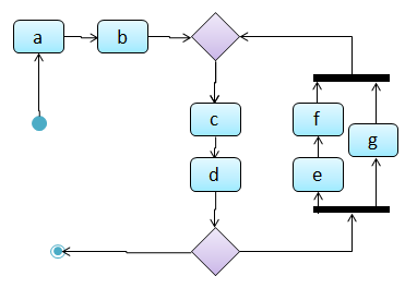
    Which of these sequences of actions is not allowed by the given activity diagram?

    • i. start a b c d end
    • ii. start a b c d e f g c d end
    • iii. start a b c d e g f c d end
    • iv. start a b c d g c d end

    (iv)

    Explanation: -e-f- and -g- are parallel paths. Both paths should complete before the execution reaches c again.

    Draw an activity diagram to represent the following workflow a burger shop uses when processing an order by a customer.

    • First, a cashier takes the order.
    • Then, three workers start preparing the order at the same time; one prepares the drinks, one prepares the burgers, and one prepares the desserts.
    • In the meantime, the customer pays for the order. If the customer has a voucher, she pays using the voucher; otherwise she pays using cash.
    • After paying, the customer collects the food after all three parts of the order are ready.


    [source:wikipeida]

    W9.2b

    Design → Modelling → Modelling Behaviors Activity diagrams - intermediate

    Can use intermediate-level activity diagrams

    Follow up notes for the item(s) above:

    Here is an example that shows the steps of drawing an activity diagram to match a given workflow.

    Video Activity diagram for the do-while loop

    Guidance for the item(s) below:

    A few weeks ago, you learned how to interpret UML diagrams. More recently, you learned how to draw diagrams to match code. There's a third use of models: as an aid for coming up with a design before the code is written.

    While this module doesn't ask you to come up with detailed designs before writing code (i.e., our approach leans closer to the agile design rather than the full design upfront approach), this third use of models come in handy at times. Let's learn a bit about that too.

    [W9.3] Conceptualizing a Design

    W9.3a

    Design → Modeling → Modeling a Solution → Introduction

    Can explain how modeling can be used before implementation

    You can use models to analyze and design software before you start coding.

    Suppose you are planning to implement a simple minesweeper game that has a text based UI and a GUI. Given below is a possible OOP design for the game.

    Before jumping into coding, you may want to find out things such as,

    • Is this class structure able to produce the behavior you want?
    • What API should each class have?
    • Do you need more classes?

    To answer these questions, you can analyze how the objects of these classes will interact with each other to produce the behavior you want.

    W9.3b

    Design → Modeling → Modeling a Solution → Basic

    Can use simple class diagrams and sequence diagrams to model an OO solution

    As mentioned in [Design → Modeling → Modeling a Solution → Introduction], this is the Minesweeper design you have come up with so far. Our objective is to analyze, evaluate, and refine that design.

    Design → Modeling → Modeling a Solution →

    Introduction

    You can use models to analyze and design software before you start coding.

    Suppose you are planning to implement a simple minesweeper game that has a text based UI and a GUI. Given below is a possible OOP design for the game.

    Before jumping into coding, you may want to find out things such as,

    • Is this class structure able to produce the behavior you want?
    • What API should each class have?
    • Do you need more classes?

    To answer these questions, you can analyze how the objects of these classes will interact with each other to produce the behavior you want.

    Let us start by modeling a sample interaction between the person playing the game and the TextUi object.
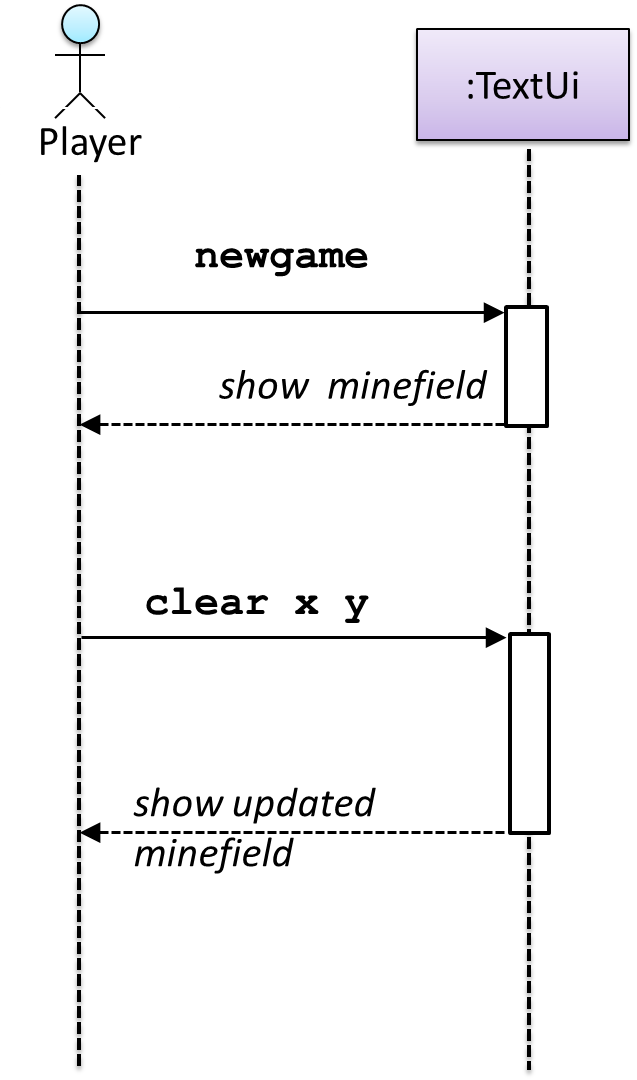
    newgame and clear x y represent commands typed by the Player on the TextUi.

    How does the TextUi object carry out the requests it has received from the player? It would need to interact with other objects of the system. Because the Logic class is the one that controls the game logic, the TextUi needs to collaborate with Logic to fulfill the newgame request. Let us extend the model to capture that interaction.
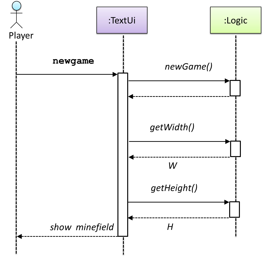
    W = Width of the minefield; H = Height of the minefield

    The above diagram assumes that W and H are the only information TextUi requires to display the minefield to the Player. Note that there could be other ways of doing this.

    The Logic methods you conceptualized in our modeling so far are:

    Now, let us look at what other objects and interactions are needed to support the newGame() operation. It is likely that a new Minefield object is created when the newGame() method is called.
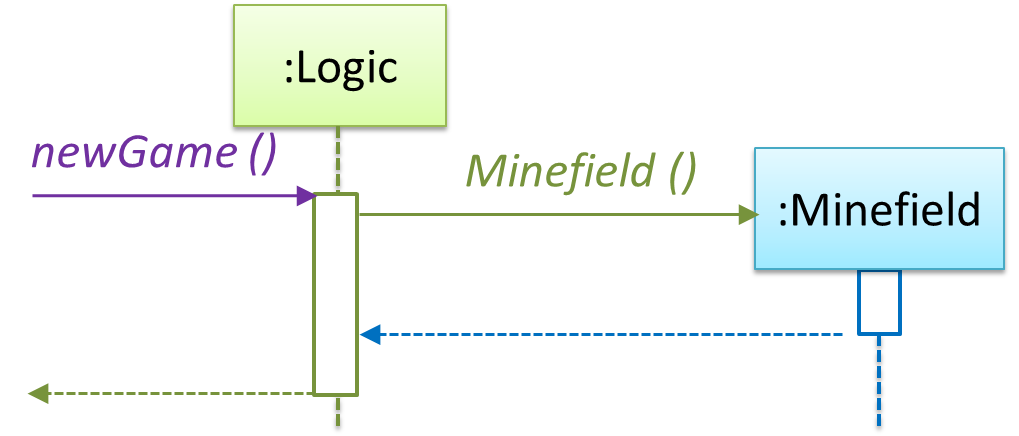
    Note that the behavior of the Minefield constructor has been abstracted away. It can be designed at a later stage.

    Given below are the interactions between the player and the TextUi for the whole game.
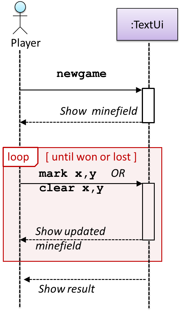
    Note that using sequence diagramsa similar technique can be used when discovering/defining the architecture-level APIs.

    Defining the architecture-level APIs for a small Tic-Tac-Toe game:
    W9.3c : OPTIONAL

    Design → Modeling → Modeling a Solution → Intermediate

    Can use intermediate class diagram and sequence diagram concepts to model an OO design

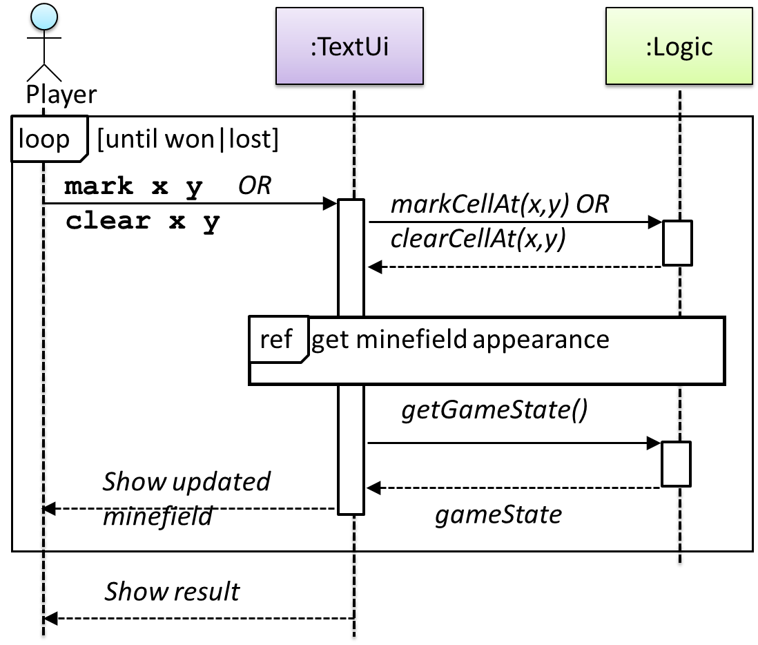
    Continuing with the example in [Design → Modeling → Modeling a Solution → Basic], next let us model how the TextUi interacts with the Logic to support the mark and clear operations until the game is won or lost.

    Design → Modeling → Modeling a Solution →

    Basic

    As mentioned in [Design → Modeling → Modeling a Solution → Introduction], this is the Minesweeper design you have come up with so far. Our objective is to analyze, evaluate, and refine that design.

    Design → Modeling → Modeling a Solution →

    Introduction

    You can use models to analyze and design software before you start coding.

    Suppose you are planning to implement a simple minesweeper game that has a text based UI and a GUI. Given below is a possible OOP design for the game.

    Before jumping into coding, you may want to find out things such as,

    • Is this class structure able to produce the behavior you want?
    • What API should each class have?
    • Do you need more classes?

    To answer these questions, you can analyze how the objects of these classes will interact with each other to produce the behavior you want.

    Let us start by modeling a sample interaction between the person playing the game and the TextUi object.

    newgame and clear x y represent commands typed by the Player on the TextUi.

    How does the TextUi object carry out the requests it has received from the player? It would need to interact with other objects of the system. Because the Logic class is the one that controls the game logic, the TextUi needs to collaborate with Logic to fulfill the newgame request. Let us extend the model to capture that interaction.

    W = Width of the minefield; H = Height of the minefield

    The above diagram assumes that W and H are the only information TextUi requires to display the minefield to the Player. Note that there could be other ways of doing this.

    The Logic methods you conceptualized in our modeling so far are:

    Now, let us look at what other objects and interactions are needed to support the newGame() operation. It is likely that a new Minefield object is created when the newGame() method is called.

    Note that the behavior of the Minefield constructor has been abstracted away. It can be designed at a later stage.

    Given below are the interactions between the player and the TextUi for the whole game.

    Note that using sequence diagramsa similar technique can be used when discovering/defining the architecture-level APIs.

    Defining the architecture-level APIs for a small Tic-Tac-Toe game:
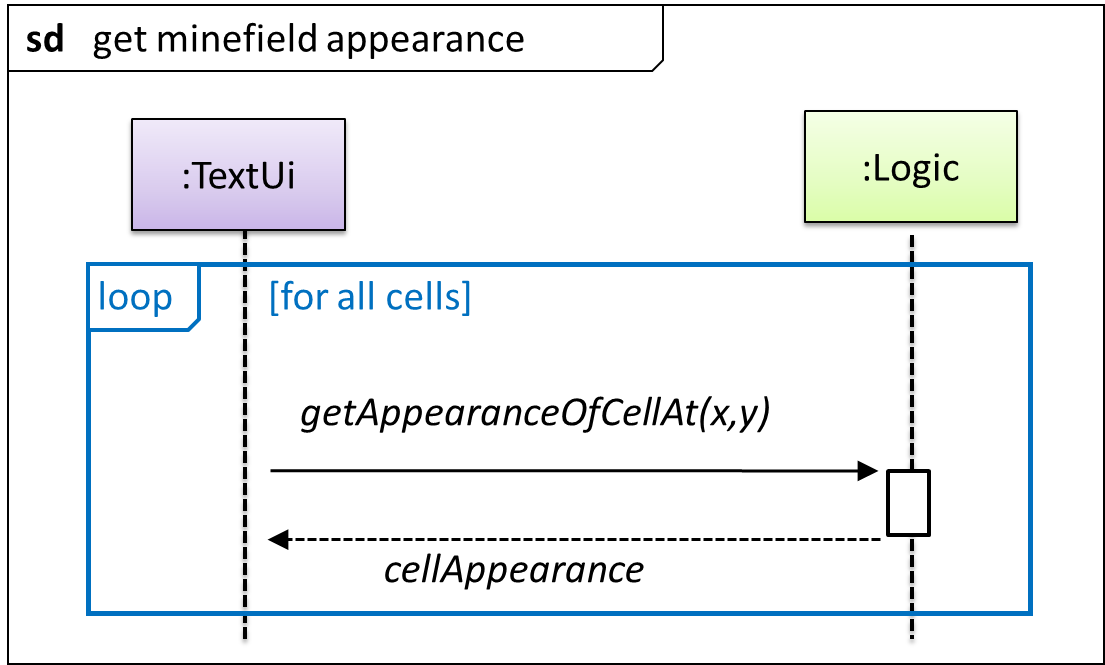
    This interaction adds the following methods to the Logic class:

    • clearCellAt(int x, int y)
    • markCellAt(int x, int y)
    • getGameState(): GAME_STATE (GAME_STATE: READY, IN_PLAY, WON, LOST, …)

    And it adds the following operation to Logic API:

    • getAppearanceOfCellAt(int,int): CELL_APPEARANCE (CELL_APPEARANCE: HIDDEN, ZERO, ONE, TWO, THREE, …, MARKED, INCORRECTLY_MARKED, INCORRECTLY_CLEARED)

    In the above design, TextUi does not access Cell objects directly. Instead, it gets values of type CELL_APPEARANCE from Logic to be displayed as a minefield to the player. Alternatively, each cell or the entire minefield can be passed directly to TextUi.

    Here is the updated class diagram:

    The above is for the case when Actor Player interacts with the system using a text UI. Additional operations (if any) required for the GUI can be discovered similarly. Suppose Logic supports a reset() operation. You can model it like this:
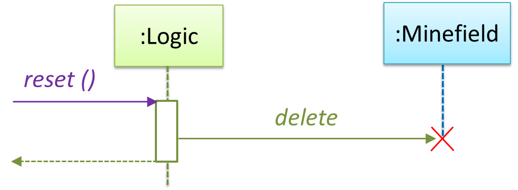
    Our current model assumes that the Minefield object has enough information (i.e. H, W, and mine locations) to create itself.

    An alternative is to have a ConfigGenerator object that generates a string containing the minefield information as shown below.
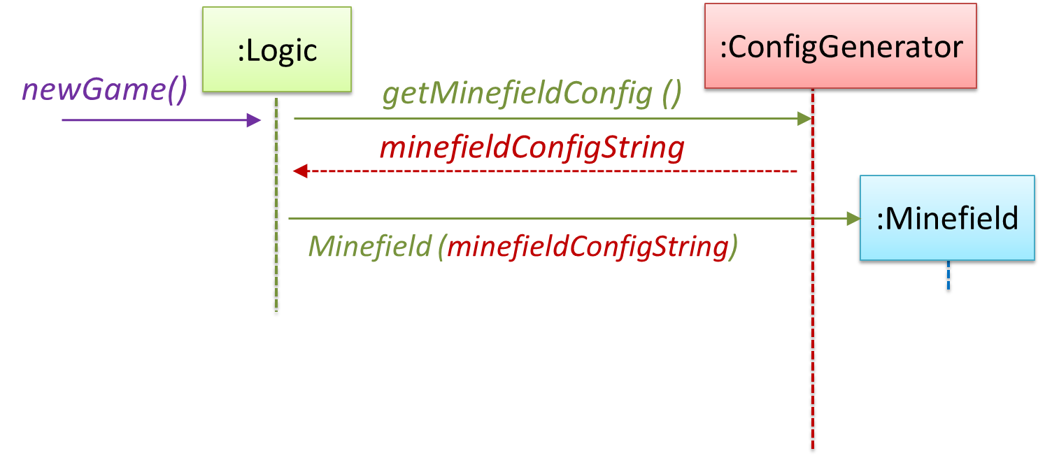
    In addition, getWidth(), getHeight(), markCellAt(x,y) and clearCellAt(x,y) can be handled like this.

    The updated class diagram:

    How is the getGameState() operation supported? Given below are two ways (there could be other ways):

    1. The Minefield class knows the state of the game at any time. The Logic class retrieves it from the Minefield class as and when required.
    2. The Logic class maintains the state of the game at all times.

    Here’s the SD for option 1.

    Here’s the SD for option 2. Assume that the game state is updated after every mark/clear action.
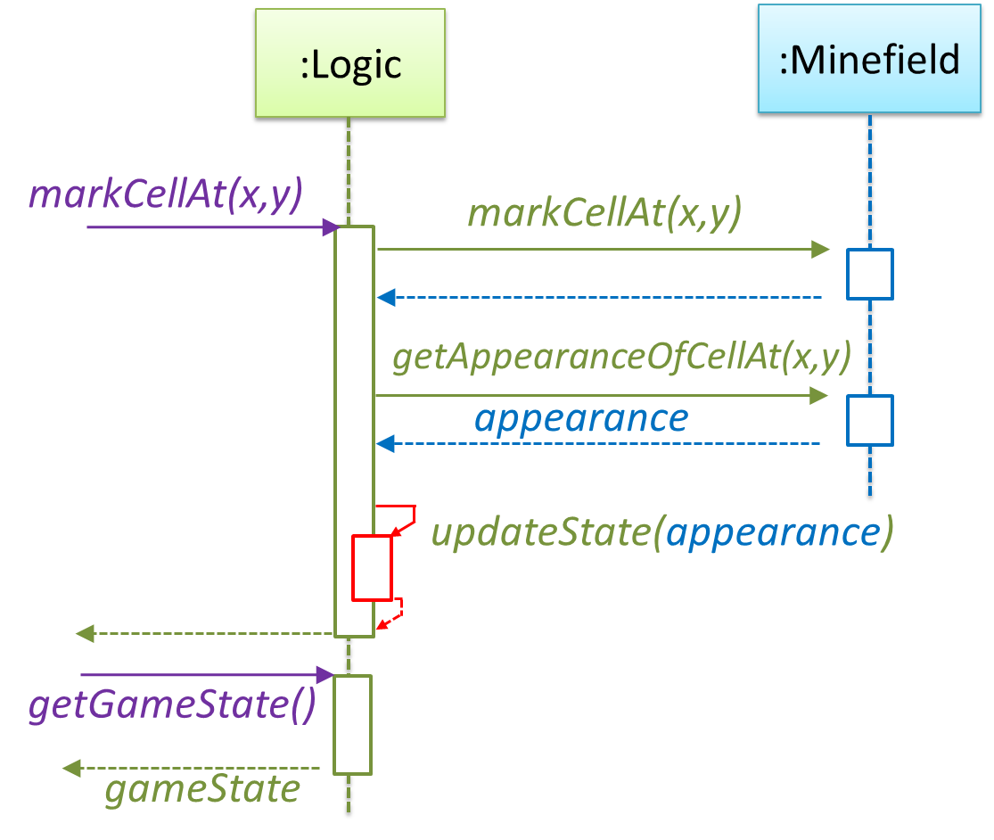
    It is now time to explore what happens inside the Minefield constructor. One way is to design it as follows.
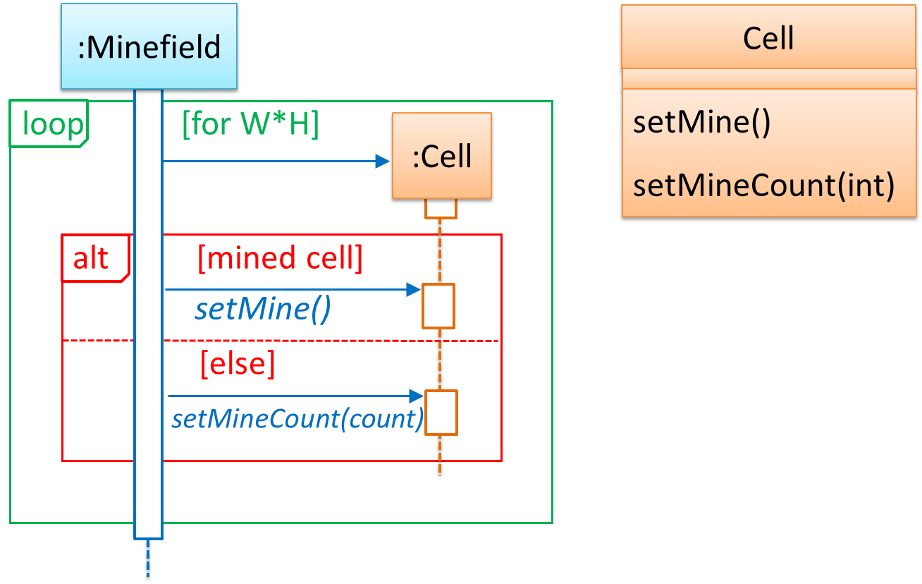
    Now let us assume that Minesweeper supports a ‘timing’ feature.

    Updated class diagram:

    When designing components, it is not necessary to draw elaborate UML diagrams capturing all details of the design. They can be done as rough sketches. For example, draw sequence diagrams only when you are not sure which operations are required by each class, or when you want to verify that your class structure can indeed support the required operations.

    Guidance for the item(s) below:

    You've already encountered architecture diagrams in your tP. Pretty soon, you might have to update that diagram to match your new product. Given below are just a brief note about drawing architecture diagrams.

    [W9.4] Architecture Diagrams: Drawing

    W9.4a

    Design → Architecture → Architecture Diagrams → Drawing

    Can draw an architecture diagram

    While architecture diagrams have no standard notation, try to follow these basic guidelines when drawing them.

    • Minimize the variety of symbols. If the symbols you choose do not have widely-understood meanings e.g. A drum symbol is widely-understood as representing a database, explain their meaning.

    • Avoid the indiscriminate use of double-headed arrows to show interactions between components.

    Consider the two architecture diagrams of the same software given below. Because Diagram 2 uses double-headed arrows, the important fact that GUI has a bi-directional dependency with the Logic component is no longer captured.

    Guidance for the item(s) below:

    These principles build on top of the design fundamentals you learned earlier (i.e., abstraction, coupling, cohesion).

    [W9.5] Design Principles

    W9.5a

    Principles → Separation of concerns principle

    Video

    Can explain separation of concerns principle

    Separation of concerns principle (SoC): To achieve better modularity, separate the code into distinct sections, such that each section addresses a separate concern. -- Proposed by Edsger W. Dijkstra

    A concern in this context is a set of information that affects the code of a computer program.

    Examples for concerns:

    • A specific feature, such as the code related to the add employee feature
    • A specific aspect, such as the code related to persistence or security
    • A specific entity, such as the code related to the Employee entity

    Applying Separation of ConcernsSoC reduces functional overlaps among code sections and also limits the ripple effect when changes are introduced to a specific part of the system.

    If the code related to persistence is separated from the code related to security, a change to how the data are persisted will not need changes to how the security is implemented.

    This principle can be applied at the class level, as well as at higher levels.

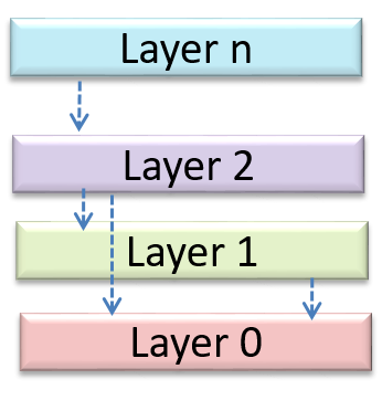
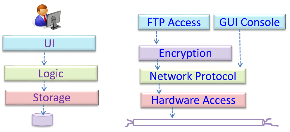
    The n-tier architecture utilizes this principle. Each layer in the architecture has a well-defined functionality that has no functional overlap with each other.

    Can identify n-tier architectural style

    In the n-tier style, higher layers make use of services provided by lower layers. Lower layers are independent of higher layers. Other names: multi-layered, layered.

    Operating systems and network communication software often use n-tier style.

    This principle should lead to higher cohesion and lower coupling.

    Can explain coupling

    Coupling is a measure of the degree of dependence between components, classes, methods, etc. Low coupling indicates that a component is less dependent on other components. High coupling (aka tight coupling or strong coupling) is discouraged due to the following disadvantages:

    • Maintenance is harder because a change in one module could cause changes in other modules coupled to it (i.e. a ripple effect).
    • Integration is harder because multiple components coupled with each other have to be integrated at the same time.
    • Testing and reuse of the module is harder due to its dependence on other modules.

    In the example below, design A appears to have more coupling between the components than design B.

    Discuss the coupling levels of alternative designs x and y.

    Overall coupling levels in x and y seem to be similar (neither has more dependencies than the other). (Note that the number of dependency links is not a definitive measure of the level of coupling. Some links may be stronger than the others.). However, in x, A is highly-coupled to the rest of the system while B, C, D, and E are standalone (do not depend on anything else). In y, no component is as highly-coupled as A of x. However, only D and E are standalone.

    Explain the link (if any) between regressions and coupling.

    When the system is highly-coupled, the risk of regressions is higher too e.g. when component A is modified, all components ‘coupled’ to component A risk ‘unintended behavioral changes’.

    Discuss the relationship between coupling and a measure of how easily a given component can be testedtestability.

    Coupling decreases testability because if the Software Under TestSUT is coupled to many other components, it becomes difficult to test the SUT in isolation of its dependencies.

    Choose the correct statements.

    • a. As coupling increases, testability decreases.
    • b. As coupling increases, the risk of regression increases.
    • c. As coupling increases, the value of automated regression testing increases.
    • d. As coupling increases, integration becomes easier as everything is connected together.
    • e. As coupling increases, maintainability decreases.

    (a)(b)(c)(d)(e)

    Explanation: High coupling means either more components are required to be integrated at once in a big-bang fashion (increasing the risk of things going wrong) or more drivers and stubs are required when integrating incrementally.

    Can explain cohesion

    Cohesion is a measure of how strongly-related and focused the various responsibilities of a component are. A highly-cohesive component keeps related functionalities together while keeping out all other unrelated things.

    Higher cohesion is better. Disadvantages of low cohesion (aka weak cohesion):

    • Lowers the understandability of modules as it is difficult to express module functionalities at a higher level.
    • Lowers maintainability because a module can be modified due to unrelated causes (reason: the module contains code unrelated to each other) or many modules may need to be modified to achieve a small change in behavior (reason: because the code related to that change is not localized to a single module).
    • Lowers reusability of modules because they do not represent logical units of functionality.

    “Only the GUI class should interact with the user. The GUI class should only concern itself with user interactions”. This statement follows from,

    • a. A software design should promote separation of concerns in a design.
    • b. A software design should increase cohesion of its components.
    • c. A software design should follow single responsibility principle.

    (a)(b)(c)

    Explanation: By making ‘user interaction’ the GUI class’s sole responsibility, we increase its cohesion. This is also in line with the separation of concerns (i.e., we separated the concern of user interaction) and the single responsibility principle (the GUI class has only one responsibility).

    W9.5b :

    Principles → Single responsibility principle

    Video

    Can explain single responsibility principle

    Single responsibility principle (SRP): A class should have one, and only one, reason to change. -- Robert C. Martin

    If a class has only one responsibility, it needs to change only when there is a change to that responsibility.

    Consider a TextUi class that does parsing of the user commands as well as interacting with the user. That class needs to change when the formatting of the UI changes as well as when the syntax of the user command changes. Hence, such a class does not follow the SRP.

    Gather together the things that change for the same reasons. Separate those things that change for different reasons. ―- Agile Software Development, Principles, Patterns, and Practices by Robert C. Martin

    W9.5c :

    Principles → Liskov substitution principle

    Video

    Can explain Liskov Substitution Principle

    Liskov substitution principle (LSP): Derived classes must be substitutable for their base classes. -- proposed by Barbara Liskov

    LSP sounds the same as substitutability but it goes beyond substitutability; LSP implies that a subclass should not be more restrictive than the behavior specified by the superclass. As you know, Java has language support for substitutability. However, if LSP is not followed, substituting a subclass object for a superclass object can break the functionality of the code.

    Paradigms → OOP → Inheritance →

    Substitutability

    Every instance of a subclass is an instance of the superclass, but not vice-versa. As a result, inheritance allows substitutability: the ability to substitute a child class object where a parent class object is expected.

    An AcademicStaff is an instance of a Staff, but a Staff is not necessarily an instance of an AcademicStaff. i.e. wherever an object of the superclass is expected, it can be substituted by an object of any of its subclasses.

    The following code is valid because an AcademicStaff object is substitutable as a Staff object.

    Staff staff = new AcademicStaff(); // OK

    But the following code is not valid because staff is declared as a Staff type and therefore its value may or may not be of type AcademicStaff, which is the type expected by variable academicStaff.

    Staff staff;
    ...
    AcademicStaff academicStaff = staff; // Not OK

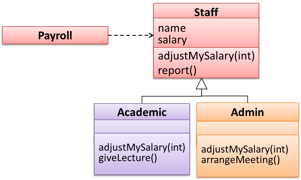
    Suppose the Payroll class depends on the adjustMySalary(int percent) method of the Staff class. Furthermore, the Staff class states that the adjustMySalary method will work for all positive percent values. Both the Admin and Academic classes override the adjustMySalary method.

    Now consider the following:

    • The Admin#adjustMySalary method works for both negative and positive percent values.
    • The Academic#adjustMySalary method works for percent values 1..100 only.

    In the above scenario,

    • The Admin class follows LSP because it fulfills Payroll’s expectation of Staff objects (i.e. it works for all positive values). Substituting Admin objects for Staff objects will not break the Payroll class functionality.
    • The Academic class violates LSP because it will not work for percent values over 100 as expected by the Payroll class. Substituting Academic objects for Staff objects can potentially break the Payroll class functionality.

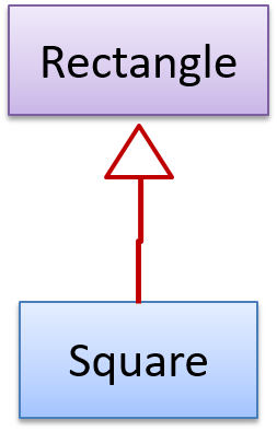
    The Rectangle#resize() method can take any integers for height and width. This contract is violated by the subclass Square#resize() because it does not accept a height that is different from the width.

    class Rectangle {
    ...
    /** sets the size to the given height and width*/
    void resize(int height, int width) {
    ...
    }
    }


    class Square extends Rectangle {

    @Override
    void resize(int height, int width) {
    if (height != width) {
    //error
    }
    }
    }

    Now consider the following method that is written to work with the Rectangle class.

    void makeSameSize(Rectangle original, Rectangle toResize) {
    toResize.resize(original.getHeight(), original.getWidth());
    }

    This code will fail if it is called as makeSameSize(new Rectangle(12, 8), new Square(4, 4)). That is, the Square class is not substitutable for the Rectangle class.

    If a subclass imposes more restrictive conditions than its parent class, it violates Liskov Substitution Principle.

    True.

    Explanation: If the subclass is more restrictive than the parent class, code that worked with the parent class may not work with the child class. Hence, the substitutability does not exist and LSP is violated.

    W9.5d :

    Principles → Open-closed principle

    Video

    Can explain open-closed principle (OCP)

    The Open-Closed Principle aims to make a code entity easy to adapt and reuse without needing to modify the code entity itself.

    Open-closed principle (OCP): A module should be open for extension but closed for modification. That is, modules should be written so that they can be extended, without requiring them to be modified. -- proposed by Bertrand Meyer

    In object-oriented programming, OCP can be achieved in various ways. This often requires separating the specification (i.e. interface) of a module from its implementation.

    In the design given below, the behavior of the CommandQueue class can be altered by adding more concrete Command subclasses. For example, by including a Delete class alongside List, Sort, and Reset, the CommandQueue can now perform delete commands without modifying its code at all. That is, its behavior was extended without having to modify its code. Hence, it is open to extensions, but closed to modification.

    The behavior of a Java generic class can be altered by passing it a different class as a parameter. In the code below, the ArrayList class behaves as a container of Students in one instance and as a container of Admin objects in the other instance, without having to change its code. That is, the behavior of the ArrayList class is extended without modifying its code.

    ArrayList students = new ArrayList<Student>();
    ArrayList admins = new ArrayList<Admin>();

    Which of these is closest to the meaning of the open-closed principle?

    (a)

    Explanation: Please refer the handout for the definition of OCP.

    W9.5e

    Principles → Law of Demeter

    Video

    Can explain the Law of Demeter

    Law of Demeter (LoD):

    • An object should have limited knowledge of another object.
    • An object should only interact with objects that are closely related to it.

    Also known as

    • Don’t talk to strangers.
    • Principle of least knowledge

    More concretely, a method m of an object O should invoke only the methods of the following kinds of objects:

    • The object O itself
    • Objects passed as parameters of m
    • Objects created/instantiated in m (directly or indirectly)
    • Objects from the objects that are held by instance variables ofdirect association of O

    The following code fragment violates LoD due to the following reason: while b is a ‘friend’ of foo (because it receives it as a parameter), g is a ‘friend of a friend’ (which should be considered a ‘stranger’), and g.doSomething() is analogous to ‘talking to a stranger’.

    void foo(Bar b) {
    Goo g = b.getGoo();
    g.doSomething();
    }

    LoD aims to prevent objects from navigating the internal structures of other objects.

    An analogy for LoD can be drawn from Facebook. If Facebook followed LoD, you would not be allowed to see posts of friends of friends, unless they are your friends as well. If Jake is your friend and Adam is Jake’s friend, you should not be allowed to see Adam’s posts unless Adam is a friend of yours as well.

    Explain the Law of Demeter using code examples. You are to make up your own code examples. Take Minesweeper as the basis for your code examples.

    Let us take the Logic class as an example. Assume that it has the following operation.

    setMinefield(Minefield mf): void

    Consider the following that can happen inside this operation:

    • mf.init();: this does not violate LoD since LoD allows calling operations of parameters received.
    • mf.getCell(1, 3).clear();: this violates LoD because Logic is handling Cell objects deep inside Minefield. Instead, it should be mf.clearCellAt(1, 3);.
    • timer.start();: this does not violate LoD because timer appears to be an internal component (i.e. a variable) of Logic itself.
    • Cell c = new Cell(); c.init();: this does not violate LoD because c was created inside the operation.

    This violates the Law of Demeter.

    void foo(Bar b) {
    Goo g = new Goo();
    g.doSomething();
    }

    False

    Explanation: The line g.doSomething() does not violate LoD because it is OK to invoke methods of objects created within a method.

    Pick the odd one out.

    • a. Law of Demeter.
    • b. Don’t add people to a late project.
    • c. Don’t talk to strangers.
    • d. Principle of least knowledge.
    • e. Coupling.

    (b)

    Explanation: Law of Demeter, which aims to reduce coupling, is also known as ‘Don’t talk to strangers’ and ‘Principle of least knowledge’.

    Guidance for the item(s) below:

    If you liked the principles covered above, given below are a few more widely used principles most of which are optional in this module (they were moved to the optional topics in order to reduce the module workload).

    The only examinable thing is the term SOLID principles.

    W9.5f : OPTIONAL

    Principles → Interface segregation principle

    Can explain interface segregation principle

    Interface segregation principle (ISP): No client should be forced to depend on methods it does not use.

    The Payroll class should not depend on the AdminStaff class because it does not use the arrangeMeeting() method. Instead, it should depend on the SalariedStaff interface.

    public class Payroll {
    // ...
    private void adjustSalaries(AdminStaff adminStaff) { // violates ISP
    // ...
    }

    }
    public class Payroll {
    // ...
    private void adjustSalaries(SalariedStaff staff) { // does not violate ISP
    // ...
    }
    }

    W9.5g : OPTIONAL

    Principles → Dependency inversion principle

    Can explain dependency inversion principle (DIP)

    Dependency inversion principle (DIP):

    1. High-level modules should not depend on low-level modules. Both should depend on abstractions.
    2. Abstractions should not depend on details. Details should depend on abstractions.

    Example:

    In design (a), the higher level class Payroll depends on the lower level class Employee, which is a violation of DIP. In design (b), both Payroll and Employee depend on the Payee interface (note that inheritance is a dependency).

    Design (b) is more flexible (and less coupled) because now the Payroll class need not change when the Employee class changes.

    Which of these statements is true about the Dependency Inversion Principle?

    • a. It can complicate the design/implementation by introducing extra abstractions, but it has some benefits.
    • b. It is often used during testing to replace dependencies with mocks.
    • c. It reduces dependencies in a design.
    • d. It advocates making higher level classes depend on lower level classes.

    a

    Explanation: Replacing dependencies with mocks is Dependency Injection, not DIP. DIP does not reduce dependencies, rather, it changes the direction of dependencies. Yes, it can introduce extra abstractions but often the benefit can outweigh the extra complications.

    W9.5h

    Principles → SOLID principles

    Can explain SOLID Principles

    The five OOP principles given below are known as SOLID Principles (an acronym made up of the first letter of each principle):

    Principles →

    Single responsibility principle

    Single responsibility principle (SRP): A class should have one, and only one, reason to change. -- Robert C. Martin

    If a class has only one responsibility, it needs to change only when there is a change to that responsibility.

    Consider a TextUi class that does parsing of the user commands as well as interacting with the user. That class needs to change when the formatting of the UI changes as well as when the syntax of the user command changes. Hence, such a class does not follow the SRP.

    Gather together the things that change for the same reasons. Separate those things that change for different reasons. ―- Agile Software Development, Principles, Patterns, and Practices by Robert C. Martin

    Principles →

    Open-closed principle

    The Open-Closed Principle aims to make a code entity easy to adapt and reuse without needing to modify the code entity itself.

    Open-closed principle (OCP): A module should be open for extension but closed for modification. That is, modules should be written so that they can be extended, without requiring them to be modified. -- proposed by Bertrand Meyer

    In object-oriented programming, OCP can be achieved in various ways. This often requires separating the specification (i.e. interface) of a module from its implementation.

    In the design given below, the behavior of the CommandQueue class can be altered by adding more concrete Command subclasses. For example, by including a Delete class alongside List, Sort, and Reset, the CommandQueue can now perform delete commands without modifying its code at all. That is, its behavior was extended without having to modify its code. Hence, it is open to extensions, but closed to modification.

    The behavior of a Java generic class can be altered by passing it a different class as a parameter. In the code below, the ArrayList class behaves as a container of Students in one instance and as a container of Admin objects in the other instance, without having to change its code. That is, the behavior of the ArrayList class is extended without modifying its code.

    ArrayList students = new ArrayList<Student>();
    ArrayList admins = new ArrayList<Admin>();

    Which of these is closest to the meaning of the open-closed principle?

    (a)

    Explanation: Please refer the handout for the definition of OCP.

    Principles →

    Liskov substitution principle

    Liskov substitution principle (LSP): Derived classes must be substitutable for their base classes. -- proposed by Barbara Liskov

    LSP sounds the same as substitutability but it goes beyond substitutability; LSP implies that a subclass should not be more restrictive than the behavior specified by the superclass. As you know, Java has language support for substitutability. However, if LSP is not followed, substituting a subclass object for a superclass object can break the functionality of the code.

    Paradigms → OOP → Inheritance →

    Substitutability

    Every instance of a subclass is an instance of the superclass, but not vice-versa. As a result, inheritance allows substitutability: the ability to substitute a child class object where a parent class object is expected.

    An AcademicStaff is an instance of a Staff, but a Staff is not necessarily an instance of an AcademicStaff. i.e. wherever an object of the superclass is expected, it can be substituted by an object of any of its subclasses.

    The following code is valid because an AcademicStaff object is substitutable as a Staff object.

    Staff staff = new AcademicStaff(); // OK

    But the following code is not valid because staff is declared as a Staff type and therefore its value may or may not be of type AcademicStaff, which is the type expected by variable academicStaff.

    Staff staff;
    ...
    AcademicStaff academicStaff = staff; // Not OK

    Suppose the Payroll class depends on the adjustMySalary(int percent) method of the Staff class. Furthermore, the Staff class states that the adjustMySalary method will work for all positive percent values. Both the Admin and Academic classes override the adjustMySalary method.

    Now consider the following:

    • The Admin#adjustMySalary method works for both negative and positive percent values.
    • The Academic#adjustMySalary method works for percent values 1..100 only.

    In the above scenario,

    • The Admin class follows LSP because it fulfills Payroll’s expectation of Staff objects (i.e. it works for all positive values). Substituting Admin objects for Staff objects will not break the Payroll class functionality.
    • The Academic class violates LSP because it will not work for percent values over 100 as expected by the Payroll class. Substituting Academic objects for Staff objects can potentially break the Payroll class functionality.

    The Rectangle#resize() method can take any integers for height and width. This contract is violated by the subclass Square#resize() because it does not accept a height that is different from the width.

    class Rectangle {
    ...
    /** sets the size to the given height and width*/
    void resize(int height, int width) {
    ...
    }
    }


    class Square extends Rectangle {

    @Override
    void resize(int height, int width) {
    if (height != width) {
    //error
    }
    }
    }

    Now consider the following method that is written to work with the Rectangle class.

    void makeSameSize(Rectangle original, Rectangle toResize) {
    toResize.resize(original.getHeight(), original.getWidth());
    }

    This code will fail if it is called as makeSameSize(new Rectangle(12, 8), new Square(4, 4)). That is, the Square class is not substitutable for the Rectangle class.

    If a subclass imposes more restrictive conditions than its parent class, it violates Liskov Substitution Principle.

    True.

    Explanation: If the subclass is more restrictive than the parent class, code that worked with the parent class may not work with the child class. Hence, the substitutability does not exist and LSP is violated.

    Principles →

    Interface segregation principle

    Interface segregation principle (ISP): No client should be forced to depend on methods it does not use.

    The Payroll class should not depend on the AdminStaff class because it does not use the arrangeMeeting() method. Instead, it should depend on the SalariedStaff interface.

    public class Payroll {
    // ...
    private void adjustSalaries(AdminStaff adminStaff) { // violates ISP
    // ...
    }

    }
    public class Payroll {
    // ...
    private void adjustSalaries(SalariedStaff staff) { // does not violate ISP
    // ...
    }
    }

    Principles →

    Dependency inversion principle

    Dependency inversion principle (DIP):

    1. High-level modules should not depend on low-level modules. Both should depend on abstractions.
    2. Abstractions should not depend on details. Details should depend on abstractions.

    Example:

    In design (a), the higher level class Payroll depends on the lower level class Employee, which is a violation of DIP. In design (b), both Payroll and Employee depend on the Payee interface (note that inheritance is a dependency).

    Design (b) is more flexible (and less coupled) because now the Payroll class need not change when the Employee class changes.

    Which of these statements is true about the Dependency Inversion Principle?

    • a. It can complicate the design/implementation by introducing extra abstractions, but it has some benefits.
    • b. It is often used during testing to replace dependencies with mocks.
    • c. It reduces dependencies in a design.
    • d. It advocates making higher level classes depend on lower level classes.

    a

    Explanation: Replacing dependencies with mocks is Dependency Injection, not DIP. DIP does not reduce dependencies, rather, it changes the direction of dependencies. Yes, it can introduce extra abstractions but often the benefit can outweigh the extra complications.

    W9.5i : OPTIONAL

    Principles → YAGNI principle

    Can explain YAGNI principle

    YAGNI (You Aren't Gonna Need It!) Principle: Do not add code simply because ‘you might need it in the future’.

    The principle says that some capability you presume your software needs in the future should not be built now because chances are "you aren't gonna need it". The rationale is that you do not have perfect information about the future and therefore some of the extra work you do to fulfill a potential future need might go to waste when some of your predictions fail to materialize.

    • Yagni -- A detailed article explaining YAGNI, written by Martin Fowler.

    W9.5j : OPTIONAL

    Principles → DRY principle

    Can explain DRY principle

    DRY (Don't Repeat Yourself) principle: Every piece of knowledge must have a single, unambiguous, authoritative representation within a system. -- The Pragmatic Programmer, by Andy Hunt and Dave Thomas

    This principle guards against the duplication of information.

    A functionality being implemented twice is a violation of the DRY principle even if the two implementations are different.

    The value of a system-wide timeout being defined in multiple places is a violation of DRY.

    W9.5k : OPTIONAL

    Principles → Brooks' law

    Can explain Brooks' law

    Brooks' law: Adding people to a late project will make it later. -- Fred Brooks (author of The Mythical Man-Month)

    Explanation: The additional communication overhead will outweigh the benefit of adding extra manpower, especially if done near a deadline.

    Does the Brook’s Law apply to a school project? Justify.

    Yes. Adding a new student to a project team can result in a slow-down of the project for a short period. This is because the new member needs time to learn the project and existing members will have to spend time helping the new member get up to speed. If the project is already behind schedule and near a deadline, this could delay the delivery even further.

    Which one of these (all attributed to Fred Brooks, the author of the famous SE book The Mythical Man-Month), is called the Brook’s law?

    • a. All programmers are optimists.
    • b. Good judgement comes from experience, and experience comes from bad judgement.
    • c. The bearing of a child takes nine months, no matter how many women are assigned.
    • d. Adding more manpower to an already late project makes it even later.

    (d)

    Guidance for the item(s) below:

    Remember these three topics that we covered early in the module?

    [W9.6] [Revisiting] SDLC Process Models

    W9.6a

    Project Management → SDLC Process Models → Introduction → What

    Can explain SDLC process models

    Software development goes through different stages such as requirements, analysis, design, implementation and testing. These stages are collectively known as the software development life cycle (SDLC). There are several approaches, known as software development life cycle models (also called software process models), that describe different ways to go through the SDLC. Each process model prescribes a "roadmap" for the software developers to manage the development effort. The roadmap describes the aims of the development stage(s), the artifacts or outcome of each stage, as well as the workflow i.e. the relationship between stages.

    W9.6b

    Project Management → SDLC Process Models → Introduction → Sequential models

    Can explain sequential process models

    The sequential model, also called the waterfall model, models software development as a linear process, in which the project is seen as progressing steadily in one direction through the development stages. The name waterfall stems from how the model is drawn to look like a waterfall (see below).

    When one stage of the process is completed, it should produce some artifacts to be used in the next stage. For example, upon completion of the requirements stage, a comprehensive list of requirements is produced that will see no further modifications. A strict application of the sequential model would require each stage to be completed before starting the next.

    This could be a useful model when the problem statement is well-understood and stable. In such cases, using the sequential model should result in a timely and systematic development effort, provided that all goes well. As each stage has a well-defined outcome, the progress of the project can be tracked with relative ease.

    The major problem with this model is that the requirements of a real-world project are rarely well-understood at the beginning and keep changing over time. One reason for this is that users are generally not aware of how a software application can be used without prior experience in using a similar application.

    W9.6c

    Project Management → SDLC Process Models → Introduction → Iterative models

    Can explain iterative process models

    The iterative model (sometimes called iterative and incremental) advocates having several iterations of SDLC. Each of the iterations could potentially go through all the development stages, from requirements gathering to testing & deployment. Roughly, it appears to be similar to several cycles of the sequential model.

    In this model, each of the iterations produces a new version of the product. Feedback on the new version can then be fed to the next iteration. Taking the Minesweeper game as an example, the iterative model will deliver a fully playable version from the early iterations. However, the first iteration will have primitive functionality, for example, a clumsy text based UI, fixed board size, limited randomization, etc. These functionalities will then be improved in later releases.

    The iterative model can take a breadth-first or a depth-first approach to iteration planning.

    • breadth-first: an iteration evolves all major components in parallel e.g., add a new feature fully, or enhance an existing feature.
    • depth-first: an iteration focuses on fleshing out only some components e.g., update the backend to support a new feature that will be added in a future iteration.

    Most projects use a mixture of breadth-first and depth-first iterations i.e., an iteration can contain some breadth-first work as well as some depth-first work.

    Guidance for the item(s) below:

    Let's continue that thread to learn about some SDLC process models that are commonly used in the industry.

    [W9.7] SDLC Process Models (continued)

    Video

    W9.7a

    Project Management → SDLC Process Models → Introduction → Agile models

    Can explain agile process models

    In 2001, a group of prominent software engineering practitioners met and brainstormed for an alternative to documentation-driven, heavyweight software development processes that were used in most large projects at the time. This resulted in something called the agile manifesto (a vision statement of what they were looking to do).

    You are uncovering better ways of developing software by doing it and helping others do it.

    Through this work you have come to value:

    • Individuals and interactions over processes and tools
    • Working software over comprehensive documentation
    • Customer collaboration over contract negotiation
    • Responding to change over following a plan

    That is, while there is value in the items on the right, you value the items on the left more.
    -- Extract from the Agile Manifesto

    Subsequently, some of the signatories of the manifesto went on to create process models that try to follow it. These processes are collectively called agile processes. Some of the key features of agile approaches are:

    • Requirements are prioritized based on the needs of the user, are clarified regularly (at times almost on a daily basis) with the entire project team, and are factored into the development schedule as appropriate.
    • Instead of doing a very elaborate and detailed design and a project plan for the whole project, the team works based on a rough project plan and a high level design that evolves as the project goes on.
    • There is a strong emphasis on complete transparency and responsibility sharing among the team members. The team is responsible together for the delivery of the product. Team members are accountable, and regularly and openly share progress with each other and with the user.

    There are a number of agile processes in the development world today. eXtreme Programming (XP) and Scrum are two of the well-known ones.

    Choose the correct statements about agile processes.

    • a. They value working software over comprehensive documentation.
    • b. They value responding to change over following a plan.
    • c. They may not be suitable for some type of projects.
    • d. XP and Scrum are agile processes.

    (a)(b)(c)(d)

    W9.7b

    Project Management → SDLC Process Models → Scrum

    Can explain scrum

    This description of Scrum was adapted from Wikipedia [retrieved on 18/10/2011], emphasis added:

    Scrum is a process skeleton that contains sets of practices and predefined roles. The main roles in Scrum are:

    • The Scrum Master, who maintains the processes (typically in lieu of a project manager)
    • The Product Owner, who represents the stakeholders and the business
    • The Team, a cross-functional group who do the actual analysis, design, implementation, testing, etc.

    A Scrum project is divided into iterations called Sprints. A sprint is the basic unit of development in Scrum. Sprints tend to last between one week and one month, and are a timeboxed (i.e. restricted to a specific duration) effort of a constant length.

    Each sprint is preceded by a planning meeting, where the tasks for the sprint are identified and an estimated commitment for the sprint goal is made, and followed by a review or retrospective meeting, where the progress is reviewed and lessons for the next sprint are identified.

    During each sprint, the team creates a potentially deliverable product increment (for example, working and tested software). The set of features that go into a sprint come from the product backlog, which is a prioritized set of high level requirements of work to be done. Which backlog items go into the sprint is determined during the sprint planning meeting. During this meeting, the Product Owner informs the team of the items in the product backlog that he or she wants completed. The team then determines how much of this they can commit to complete during the next sprint, and records this in the sprint backlog. During a sprint, no one is allowed to change the sprint backlog, which means that the requirements are frozen for that sprint. Development is timeboxed such that the sprint must end on time; if requirements are not completed for any reason they are left out and returned to the product backlog. After a sprint is completed, the team demonstrates the use of the software.

    Scrum enables the creation of self-organizing teams by encouraging co-location of all team members, and verbal communication between all team members and disciplines in the project.

    A key principle of Scrum is its recognition that during a project the customers can change their minds about what they want and need (often called requirements churn), and that unpredicted challenges cannot be easily addressed in a traditional predictive or planned manner. As such, Scrum adopts an empirical approach—accepting that the problem cannot be fully understood or defined, focusing instead on maximizing the team’s ability to deliver quickly and respond to emerging requirements.

    Daily Scrum is another key scrum practice. The description below was adapted from https://www.mountaingoatsoftware.com (emphasis added):

    In Scrum, on each day of a sprint, the team holds a daily scrum meeting called the "daily scrum.” Meetings are typically held in the same location and at the same time each day. Ideally, a daily scrum meeting is held in the morning, as it helps set the context for the coming day's work. These scrum meetings are strictly time-boxed to 15 minutes. This keeps the discussion brisk but relevant.

    ...

    During the daily scrum, each team member answers the following three questions:

    • What did you do yesterday?
    • What will you do today?
    • Are there any impediments in your way?

    ...

    The daily scrum meeting is not used as a problem-solving or issue resolution meeting. Issues that are raised are taken offline and usually dealt with by the relevant subgroup immediately after the meeting.

    (This is not an endorsement of the product mentioned in the video)

    W9.7c

    Project Management → SDLC Process Models → XP

    Can explain XP

    The following description was adapted from the XP home page, emphasis added:

    Extreme Programming (XP) stresses customer satisfaction. Instead of delivering everything you could possibly want on some date far in the future, this process delivers the software you need as you need it.

    XP aims to empower developers to confidently respond to changing customer requirements, even late in the life cycle.

    XP emphasizes teamwork. Managers, customers, and developers are all equal partners in a collaborative team. XP implements a simple, yet effective environment enabling teams to become highly productive. The team self-organizes around the problem to solve it as efficiently as possible.

    XP aims to improve a software project in five essential ways: communication, simplicity, feedback, respect, and courage. Extreme Programmers constantly communicate with their customers and fellow programmers. They keep their design simple and clean. They get feedback by testing their software starting on day one. Every small success deepens their respect for the unique contributions of each and every team member. With this foundation, Extreme Programmers are able to courageously respond to changing requirements and technology.

    XP has a set of simple rules. XP is a lot like a jig saw puzzle with many small pieces. Individually the pieces make no sense, but when combined together a complete picture can be seen. This flow chart shows how Extreme Programming's rules work together.

    Pair programming, CRC cards, project velocity, and standup meetings are some interesting topics related to XP. Refer to extremeprogramming.org to find out more about XP.

    W9.7d : OPTIONAL

    Project Management → SDLC Process Models → Unified process

    Can explain the Unified Process

    The unified process is developed by the Three Amigos - Ivar Jacobson, Grady Booch and James Rumbaugh (the creators of UML).

    The unified process consists of four phases: inception, elaboration, construction and transition. The main purpose of each phase can be summarized as follows:

    Phase Activities Typical Artifacts
    Inception
    • Understand the problem and requirements
    • Communicate with customer
    • Plan the development effort
    • Basic use case model
    • Rough project plan
    • Project vision and scope
    Elaboration
    • Refine and expand requirements
    • Determine a high-level design e.g. system architecture
    • System architecture
    • Various design models
    • Prototype
    Construction
    • Major implementation effort to support the use cases identified
    • Design models are refined and fleshed out
    • Testing of all levels are carried out
    • Multiple releases of the system
    • Test cases of all levels
    • System release
    Transition
    • Ready the system for actual production use
    • Familiarize end users with the system
    • Final system release
    • Instruction manual

    Given above is a visualization of a project done using the Unified process (source: Wikipedia). As the diagram shows, a phase can consist of several iterations. Each vertical column (labeled “I1” “E1”, “E2”, “C1”, etc.) represents a single iteration. Each of the iterations consists of a set of ‘workflows’ such as ‘Business modeling’, ‘Requirements’, ‘Analysis & Design’, etc. The shaded region indicates the amount of resources and effort spent on a particular workflow in a particular iteration.

    Unified process is a flexible and customizable process model framework rather than a single fixed process. For example, the number of iterations in each phase, definition of workflows, and the intensity of a given workflow in a given iteration can be adjusted according to the nature of the project. Take the Construction Phase: to develop a simple system, one or two iterations would be sufficient. For a more complicated system, multiple iterations will be more helpful. Therefore, the diagram above simply records a particular application of the UP rather than prescribe how the UP is to be applied. However, this record can be refined and reused for similar future projects.

    Choose the correct statements about the unified process.

    • a. It was conceived by the three amigos who also created UML.
    • b. The Unified process requires the use of UML.
    • c. The Unified process is actually a process framework rather than a fixed process.
    • d. The Unified process can be iterative and incremental.

    (a)(b)(c)(d)

    Explanation: Although UP was created by the same three amigos who created UML, the UP does not require UML.

    W9.7e : OPTIONAL

    Project Management → SDLC Process Models → CMMI

    Can explain CMMI

    CMMI (Capability Maturity Model Integration) is a process improvement approach defined by Software Engineering Institute at Carnegie Melon University. CMMI provides organizations with the essential elements of effective processes, which will improve their performance. -- adapted from http://www.sei.cmu.edu/cmmi/

    CMMI defines five maturity levels for a process and provides criteria to determine if the process of an organization is at a certain maturity level. The diagram below [taken from Wikipedia] gives an overview of the five levels.

    W9.7f

    Project Management → SDLC Process Models → Recap

    Can explain process models at a higher level

    This section has some exercises that cover multiple topics related to SDLC process models.

    Discuss how a sequential approach and an iterative approach can affect the following aspects of a project.

    a) Quality of the final product.

    b) Risk of overshooting the deadline.

    c) Total project cost.

    d) Customer satisfaction.

    e) Monitoring the project progress.

    f) Suitability for a school project.

    a) Quality of the final product:

    • Iterative: Frequent reworking can deteriorate the design. Frequent refactoring should be used to prevent this. Frequent customer feedback can help to improve the quality (i.e. quality as seen by the customer).
    • Sequential: Final quality depends on the quality of each phase. Any quality problems in any phase could result in a low quality product.

    b) Risk of overshooting the deadline.

    • Iterative: Less risk. If the last iteration got delayed, we can always deliver the previous version. However, this does not guarantee that all features promised at the beginning will be delivered by the deadline.
    • Sequential: High risk. Any delay in any phase can result in overshooting the deadline with nothing to deliver.

    c) Total project cost.

    • Iterative: We can always stop before the project budget is exceeded. However, this does not guarantee that all features promised at the beginning will be delivered under the estimated cost.
    • Sequential: The sequential model requires us to carry on even if the budget is exceeded because there is no intermediate version to fall back on.

    Iterative reworking of existing artifacts could add to the cost. However, this is “cheaper” than finding at the end that we built the wrong product.

    d) Customer satisfaction

    • Iterative: The customer gets many opportunities to guide the product in the direction he/she wants. The customer gets to change requirements even in the middle of the product's development. Both of these can increase the probability of customer satisfaction.
    • Sequential: Customer satisfaction is guaranteed only if the product was delivered as promised and if the initial requirements proved to be accurate. However, the customer is not required to do the extra work of giving frequent feedback during the project's development.

    e) Monitoring project progress

    • Iterative: Hard to measure progress against a plan, as the plan itself keeps changing.
    • Sequential: Easier to measure progress against the plan, although this does not ensure eventual success.

    f) Suitability for a school project:

    Reasons to use iterative:

    • Requirements are not fixed.
    • Overshooting the deadline is not an option.
    • Gives a chance to learn lessons from one iteration and apply them in the next.

    Sequential:

    • Can save time because we minimize rework.

    Find out more about the following three topics and give at least three arguments for and three arguments against each.

    (a) Agile processes

    (b) Pair programming

    (c) Test-driven development

    (a) Arguments in favor of agile processes:

    • More focus on customer satisfaction.
    • Less chance of building the wrong product (because of frequent customer feedback).
    • Less resources wasted on bureaucracy, over-documenting, contract negotiations.

    Arguments against agile processes (not necessarily true):

    • It is ‘just hacking’. Not very systematic. No discipline.
    • It is hard to know in advance the exact final product.
    • It does not give enough attention to documentation.
    • Lack of management control (too much freedom given to developers).

    (b) Arguments in favor of pair programming:

    • It could produce better quality code.
    • It is good to have more than one person know about any piece of code.
    • It is a way to learn from each other.
    • It can be used to train new programmers.
    • Better discipline and better time management (e.g. less likely to play Farmville while working).
    • Better morale due to more interactions with co-workers.

    Arguments against pair programming:

    • Increase in total man hours required.
    • Personality clashes between pair-members.
    • Workspaces need to be adapted to suit two developers working at one computer.
    • If pairs are rotated, one needs to know more parts of the system than in solo programming.

    (c) Arguments in favor of TDD:

    • Testing will not be neglected due to time pressure (because it is done first).
    • Forces the developer to think about what the component should be before jumping into implementing it.
    • Optimizes programmer effort (i.e. if all tests pass, there is no need to add any more functionality).
    • Forces us to automate all tests.

    Arguments against TDD (not necessarily true):

    • Since tests can be seen as ‘executable specifications’, programmers tend to neglect other forms of documentation.
    • Promotes ‘trial-and-error’ coding instead of making programmers think through their algorithms (i.e. ‘just keep hacking until all tests pass’).
    • Gives a false sense of security. (What if you forgot to test certain scenarios?)

    Not intuitive. Some programmers might resist adopting TDD.

    The sequential model and the waterfall model are the two most basic process models.

    False

    Explanation: The sequential model and the waterfall model are the same thing. The second basic model is the iterative model.

    Choose the correct statements about the sequential and iterative process models.

    • a. The sequential model organizes the project based on activities.
    • b. The iterative and incremental model organizes the project based on functionality.
    • c. The iterative model can be breadth-first or depth-first.
    • d. The iterative model is always better than the sequential model.
    • e. Compared to the sequential model, the iterative model is better at adapting to changing requirements.

    (a)(b)(c)(d)(e)

    Explanation: Both models have pros and cons. There is no definitive ‘better’ choice between the two. However, the iterative model works better in typical software projects than a purely sequential approach.

    In general, which has a higher risk of overshooting a deadline?

    (b)

    Explanation: An iterative process can meet a deadline better than a sequential process. If the last iteration got delayed, we can always deliver the previous version. However, this does not guarantee that all features promised at the beginning will be delivered on the deadline.

    Guidance for the item(s) below:

    As you will be updating documentation of your project soon, here are some guidelines to help you with that.

    [W9.8] Writing Developer Documents

    Video


    Type of Developer Docs

    W9.8a

    Implementation → Documentation → Introduction → What

    Can explain the two types of developer docs

    Developer-to-developer documentation can be in one of two forms:

    1. Documentation for developer-as-user: Software components are written by developers and reused by other developers, which means there is a need to document how such components are to be used. Such documentation can take several forms:
      • API documentation: APIs expose functionality in small-sized, independent and easy-to-use chunks, each of which can be documented systematically.
      • Tutorial-style instructional documentation: In addition to explaining functions/methods independently, some higher-level explanations of how to use an API can be useful.
    1. Documentation for developer-as-maintainer: There is a need to document how a system or a component is designed, implemented and tested so that other developers can maintain and evolve the code. Writing documentation of this type is harder because of the need to explain complex internal details. However, given that readers of this type of documentation usually have access to the source code itself, only some information needs to be included in the documentation, as code (and code comments) can also serve as a complementary source of information.

    Another view proposed by Daniele Procida in this article is as follows:

    There is a secret that needs to be understood in order to write good software documentation: there isn’t one thing called documentation, there are four. They are: tutorials, how-to guides, explanation and technical reference. They represent four different purposes or functions, and require four different approaches to their creation. Understanding the implications of this will help improve most software documentation - often immensely. ...

    TUTORIALS

    A tutorial:

    • is learning-oriented
    • allows the newcomer to get started
    • is a lesson

    Analogy: teaching a small child how to cook

    HOW-TO GUIDES

    A how-to guide:

    • is goal-oriented
    • shows how to solve a specific problem
    • is a series of steps

    Analogy: a recipe in a cookery book

    EXPLANATION

    An explanation:

    • is understanding-oriented
    • explains
    • provides background and context

    Analogy: an article on culinary social history

    REFERENCE

    A reference guide:

    • is information-oriented
    • describes the machinery
    • is accurate and complete

    Analogy: a reference encyclopedia article

    Software documentation (applies to both user-facing and developer-facing) is best kept in a text format for ease of version tracking. A writer-friendly source format is also desirable as non-programmers (e.g., technical writers) may need to author/edit such documents. As a result, formats such as Markdown, AsciiDoc, and PlantUML are often used for software documentation.

    Choose correct statements about API documentation.

    • a. They are useful for both developers who use the API and developers who maintain the API implementation.
    • b. There are tools that can generate API documents from code comments.
    • c. API documentation may contain code examples.

    All


    Guideline: Aim for Comprehensibility

    W9.8b

    Implementation → Documentation → Guidelines → Aim for Comprehensibility → What

    Can explain the need for comprehensibility in documents

    Technical documents exist to help others understand technical details. Therefore, it is not enough for the documentation to be accurate and comprehensive; it should also be comprehensible.

    W9.8c

    Implementation → Documentation → Guidelines → Aim for Comprehensibility → How

    Can write reasonably comprehensible developer documents

    Here are some tips on writing effective documentation.

    • Use plenty of diagrams: It is not enough to explain something in words; complement it with visual illustrations (e.g. a UML diagram).
    • Use plenty of examples: When explaining algorithms, show a running example to illustrate each step of the algorithm, in parallel to worded explanations.
    • Use simple and direct explanations: Convoluted explanations and fancy words will annoy readers. Avoid long sentences.
    • Get rid of statements that do not add value: For example, 'We made sure our system works perfectly' (who didn't?), 'Component X has its own responsibilities' (of course it has!).
    • It is not a good idea to have separate sections for each type of artifact, such as 'use cases', 'sequence diagrams', 'activity diagrams', etc. Such a structure, coupled with the indiscriminate inclusion of diagrams without justifying their need, indicates a failure to understand the purpose of documentation. Include diagrams when they are needed to explain something. If you want to provide additional diagrams for completeness' sake, include them in the appendix as a reference.

    It is recommended for developer documents,

    • a. to have separate sections for each type of diagrams such as class diagrams, sequence diagrams, use case diagrams etc.
    • b. to give a high priority to comprehension too, not stop at comprehensiveness only.

    (a)(b)

    Explanation:

    (a) Use diagrams when they help to understand the text descriptions. Text and diagrams should be used in tandem. Having separate sections for each diagram type is a sign of generating diagrams for the sake of having them.

    (b) Both are important, but lengthy, complete, accurate yet hard to understand documents are not that useful.


    Guideline: Describe Top-Down

    W9.8d

    Implementation → Documentation → Guidelines → Describe Top-Down → What

    Can distinguish between top-down and bottom-up documentation

    When writing project documents, a top-down breadth-first explanation is easier to understand than a bottom-up one.

    W9.8e

    Implementation → Documentation → Guidelines → Describe Top-Down → Why

    Can explain the advantages of top-down documentation

    The main advantage of the top-down approach is that the document is structured like an upside down tree (root at the top) and the reader can travel down a path she is interested in until she reaches the component she is interested to learn in-depth, without having to read the entire document or understand the whole system.

    W9.8f

    Implementation → Documentation → Guidelines → Describe Top-Down → How

    Can write documentation in a top-down manner

    To explain a system called SystemFoo with two sub-systems, FrontEnd and BackEnd, start by describing the system at the highest level of abstraction, and progressively drill down to lower level details. An outline for such a description is given below.

    [First, explain what the system is, in a black-box fashion (no internal details, only the external view).]

    SystemFoo is a ....

    [Next, explain the high-level architecture of SystemFoo, referring to its major components only.]

    SystemFoo consists of two major components: FrontEnd and BackEnd.

    The job of FrontEnd is to ... while the job of BackEnd is to ...

    And this is how FrontEnd and BackEnd work together ...

    [Now you can drill down to FrontEnd's details.]

    FrontEnd consists of three major components: A, B, C

    A's job is to ...
    B's job is to...
    C's job is to...

    And this is how the three components work together ...

    [At this point, further drill down to the internal workings of each component. A reader who is not interested in knowing the nitty-gritty details can skip ahead to the section on BackEnd.]

    In-depth description of A

    In-depth description of B

    ...

    [At this point drill down to the details of the BackEnd.]

    ...


    Guideline: Minimal but Sufficient

    W9.8g

    Implementation → Documentation → Guidelines → Minimal but Sufficient → What

    Can explain that documentation should be minimal yet sufficient

    Aim for 'just enough' developer documentation.

    • Writing and maintaining developer documents is an overhead. You should try to minimize that overhead.
    • If the readers are developers who will eventually read the code, the documentation should complement the code and should provide only just enough guidance to get started.

    W9.8h

    Implementation → Documentation → Guidelines → Minimal but Sufficient → How

    Can write minimal yet sufficient documentation

    Anything that is already clear in the code need not be described in words. Instead, focus on providing higher level information that is not readily visible in the code or comments.

    Refrain from duplicating chunks of text. When describing several similar algorithms/designs/APIs, etc., do not simply duplicate large chunks of text. Instead, describe the similarities in one place and emphasize only the differences in other places. It is very annoying to see pages and pages of similar text without any indication as to how they differ from each other.